Push-button arrangement for an electronic or electromechanical wristwatch
Active Publication Date: 2017-06-22
ETA SA MFG HORLOGERE SUISSE
View PDF1 Cites 1 Cited by
- Summary
- Abstract
- Description
- Claims
- Application Information
AI Technical Summary
Benefits of technology
The present invention provides a surface mount push-button arrangement that is easy to incorporate in small objects like wristwatches. It is more compact than traditional push-buttons and can be produced more efficiently. The printed circuit sheet, on which the push-button is welded, extends underneath the push-button and is subjected to compression rather than shear stress, reducing the risk of weld yielding. The push-button is positioned against the side of the electronic plate, providing good mechanical resistance to pressure and allowing good positioning tolerances in the vertical plane. The push-button can be welded flat on the printed circuit sheet, making manufacturing easier.
Problems solved by technology
Consequently, when the push-button is pressed, the welds are subjected to compression and not shear stress, such that the risk of the welds yielding is almost totally removed.
Method used
View moreImage
Smart ImageViewing Examples

Examples
case 4
[0029]Case 4
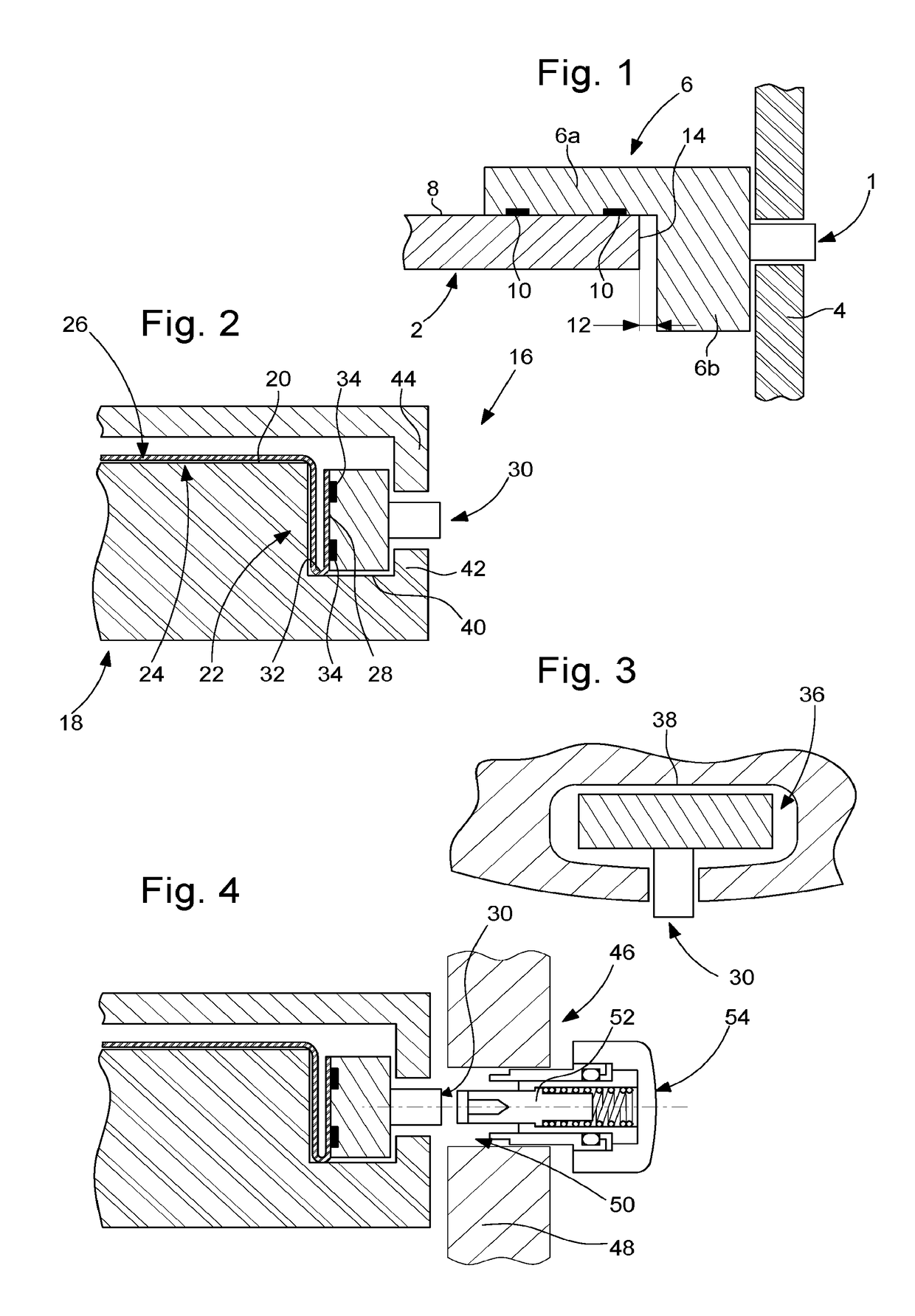
[0030]Support 6
[0031]Branches 6a, 6b
[0032]Upper surface 8
[0033]Weld spots 10
[0034]Play 12
[0035]Lateral surface 14
[0036]Push-button arrangement 16
[0037]Electronic plate 18
[0038]Peripheral edge 20
[0039]Lateral surface or side 22
[0040]Upper surface 24
[0041]Flexible printed circuit sheet 26
[0042]Free portion 28
[0043]Push-button 30
[0044]V-shaped fold 32
[0045]Welds 34
[0046]Housing 36
[0047]Vertical side wall 38
[0048]Horizontal surface 40
[0049]Edge portion 42
[0050]Additional plate 44
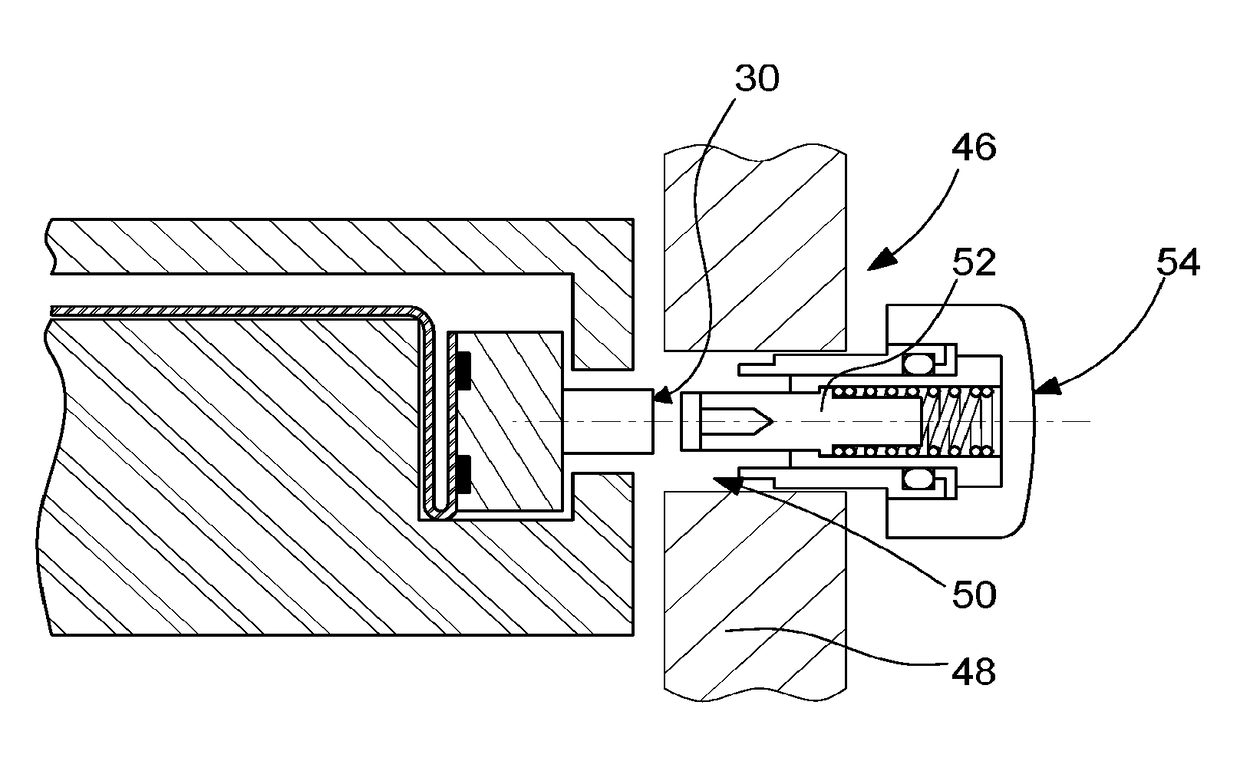
case 46
[0051]Case 46
[0052]Case middle 48
[0053]Through hole 50
[0054]Stem 52
[0055]External push-button 54
Login to View More PUM
 Abstract
A push-button arrangement includes an electronic plate. The push-button is of the type surface mounted on a flexible printed circuit sheet that is itself partially fixed to the electronic plate. A portion of the flexible printed circuit sheet that carries the push-button remains free and is folded around a peripheral edge of the electronic plate, such that the push-button extends substantially perpendicularly to the electronic plate and bears against a lateral surface of the electronic plate.
Description
FIELD OF THE INVENTION[0001]The present invention concerns a push-button arrangement for an electronic wristwatch. More particularly, the invention concerns such a push-button arrangement which is more compact and which has better fatigue resistance.BACKGROUND OF THE INVENTION[0002]A push-button is a very simple control means which consists schematically of a stem sliding in a passage through the frame of a device, while being held in a rest position by elastic means which push the head of the stem outwards, and being moved into the operating position by the user pressing on the head. The elastic means are, for example, formed by a helical spring housed inside the through passage and which is supported between the frame and the push-button head.[0003]In applications where it is easy for the user to see whether a device is operating properly, such as lighting a chamber or activating a sound source, a control means of the aforementioned type may be satisfactory, even in its simplest f...
Claims
Login to View More Application Information
Patent Timeline
 IPC IPC(8): H01H13/14G04C3/00H01H13/52
CPCH01H13/14G04C3/007H01H13/52G04G17/00G04G21/08G04B3/048G04B37/106G04G17/08H01H13/26
Inventor LAGORGETTE, PASCALBALMER, RAPHAEL
Owner ETA SA MFG HORLOGERE SUISSE