
Method For Detecting OTDR Curve Tail End Event To Locate Optical Fibre Break Point In Online Mode

a technology of optical fiber and tail end event, applied in the field of optical network, can solve the problems of jitter in the reflected light collected by the otdr, time-consuming method, and expensive hardware support, so as to reduce the effect of noise and business signal, accurately detect the location of the end event, and improve the accuracy of the detection method

Active Publication Date: 2017-06-22
ACCELINK TECHNOLOGIES CO LTD
View PDF6 Cites 11 Cited by
  • Summary
  • Abstract
  • Description
  • Claims
  • Application Information

AI Technical Summary

Benefits of technology

The invention improves the accuracy of detecting the end of an optical fiber transmission by adding a multi-case determination mechanism to detect the end event. This helps to reduce the impact of noise and business signals, allowing for precise identification of the location of the end event and the breakpoint of the optical fiber. This is particularly useful in online modems where the fiber may be constantly in use.

Problems solved by technology

Now wave division system has been popular with high outgoing optical power, which cannot be completely isolated, resulting jitter in reflected light collected by the OTDR.
On the other hand, in wavelength division system, the time of analysis is extended if the dynamic range and the number of averaging step is increased continuously, resulting nonlinear effect, and it needs expensive hardware support.
The method is time-consuming, requires large memory space.
It is difficult to establish different templates, and the overall implementation is complex.
Although this method considers two cases of the end event, such transformation makes the noise amplitude large, even larger than end reflection amplitude.
Since the end event is near tail noise, obviously, the method is likely to produce false judgment on the end.
However, online noise will produce a large amplitude of mutation, the filter cannot completely filtered the same, so this method cannot resist impact of noise.
From above, general method of OTDR detecting end events cannot effectively remove noise, distinguish various end events, and detect a variety of end event in online case, which affects reliability of optical fiber monitoring system.

Method used


Image

  • Method For Detecting OTDR Curve Tail End Event To Locate Optical Fibre Break Point In Online Mode
  • Method For Detecting OTDR Curve Tail End Event To Locate Optical Fibre Break Point In Online Mode
  • Method For Detecting OTDR Curve Tail End Event To Locate Optical Fibre Break Point In Online Mode

Examples


Embodiment Construction

[0020]The following combination of drawings and specific implementation methods are for further details of the technical scheme of the invention, the advantages and characteristics of the present invention will be described with more clearly.

[0021]Those skilled in the art will appreciate, although the following description relating to the embodiment of the invention is related to many of the technical details, but this is only used to illustrate the principle of the invention of the sample, and does not imply any restrictions. Besides the technical details of the invention can be applied to different occasions in the following examples, as long as they can not deviate from the principle and spirit of the invention.

[0022]In addition, in order to avoid the tedious manual to describe, in the description, some technical details which are available in the existing data may be omitted or simplified, it is understandable for those skilled in the art, and this will not affect the sufficient...


PUM


Abstract

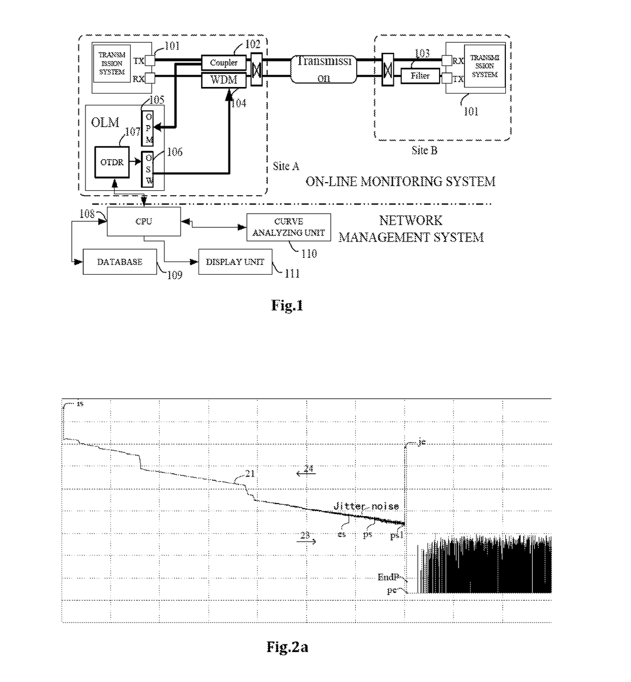
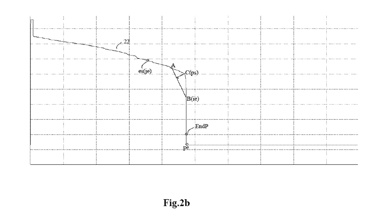
Disclosed is a method for detecting an OTDR curve tail end event to locate an optical fibre break point in an online mode, comprising following steps: 1, an OTDR emits detection light to an optical fibre operation link, and receives reflection light to form reflection sampling point data containing tail end event; 2, head end reflection point in sampling point is found out; 3, traversal is carried out to find search region end point; 4, segmented line fitting is carried out in region of [search region end point, head end reflection point] in reversed direction, start point of section of line meeting predetermined condition is used as a search region start point; 5, if absolute value of difference between largest sampling value in search region and sampling value of search region start point is larger than second preset threshold value, tail end event is judged as reflection tail end event.

Description

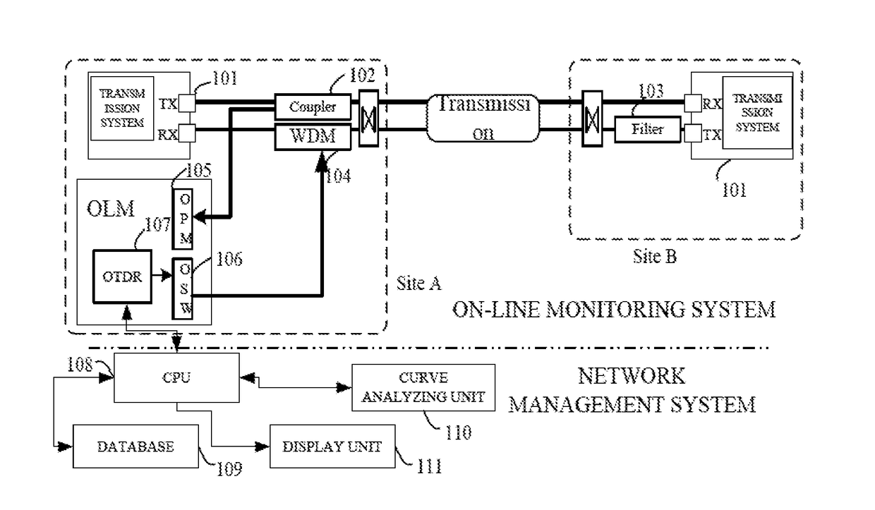
FIELD OF THE INVENTION[0001]Embodiments of the present invention relates to technical field of optical network, in particular to a method for locating breakpoint of an optical fiber by applying OTDR for end event detection in a scene of online mode.BACKGROUND OF THE INVENTION[0002]OTDR is Optical Time Domain Reflectometer. By emitting a light pulse into the fiber and receiving returned curve information, link condition is detected. When light pulse propagates within an optical fiber, scattering and reflection are generated due to property of the fiber itself, connector, fusion point, bent or other similar events. In OTDR, there are mainly Rayleigh scattering and Finel reflection, some of which will return to OTDR. The following formula shows how OTDR measures distance:d=(c×t) / 2(IOR),[0003]where d is distance (fiber length) to be measured, c is velocity of light in vacuum, IOR is index of refraction of the optical fiber, and t is total time from sending signal to receiving the same (...

Claims


Application Information

Patent Timeline
Patent Type & Authority Applications(United States)
IPC IPC(8): H04B10/071H04B10/079
CPCH04B10/0791H04B10/071
Inventor YI, SHUIHANYU, JIEKUILUO, QINGZHOU, ZHIZHUYU, LEI
Owner ACCELINK TECHNOLOGIES CO LTD
Learn More