System and method for acoustic imaging with coherent compounding using intercostal spaces

a technology of intercostal space and acoustic imaging, applied in the field of acoustic imaging apparatuses, systems and methods, can solve problems such as loss of resolution, part of the aperture may be blocked, and ultrasound imaging of the heart through the chest (transthoracic ultrasound imaging) is complicated

Active Publication Date: 2017-06-29
KONINKLJIJKE PHILIPS NV
View PDF6 Cites 4 Cited by
  • Summary
  • Abstract
  • Description
  • Claims
  • Application Information

AI Technical Summary

Benefits of technology

[0007]In some embodiments, exploiting redundancy in transmit/receive pair paths among the acoustic transducers in the acoustic transducer array to compensate for missing image data of the imaging region due to the one or more obstructions and producing an image of the imaging region from the compensated image data comprises: performing at least first and second transmit-and-receive operations using at least first and second apodization functions, including: performing the first transmit-and-receive operation by employing the acoustic transducer array to transmit a first acoustic wave to the imaging region and to receive back from the imaging region a first acoustic echo and to produce therefrom first image data, wherein the first apodization function is applied to the acoustic transducer array to produce a first transmit aperture and a first receive aperture for the first transmit-and-receive operation, and performing the second transmit-and-receive operation by employing the acoustic transducer array to transmit a second acoustic wave to the imaging region and to receive back from the imaging region a second acoustic echo and to produce therefrom second image data, wherein the second apodization function is applied to the acoustic transducer array to produce a second transmit aperture and a second receive aperture for the second transmit-and-receive operation; and producing an image of the imaging region by combining the first image data with the second image data. The at least first and second apodization functions are determined from an inverse filter for the acoustic transducer array with respect to the imaging region, wherein when the inverse filter is multiplied by an angular spectrum for the acoustic transducer array with respect to the imaging region in the presence of the one or more obstructions, it produces an ideal angular spectrum for the acoustic transducer array with respect to the imaging region which would exist in the absence of the one or more obstructions.
[0008]In some embodiments, exploiting redundancy in transmit/receive pair paths among the acoustic transducers in the acoustic transducer array to compensate for missing image data of the imaging region due to the one or more obstructions and producing an image of the imaging region from the compensated image data comprises performing an RF data (pre-detection) based or image based deconvolution algorithm.
[0009]In another aspect of the invention, an apparatus for imaging an imaging region, comprises: an acoustic transducer array configured to produce image data for the imaging region, wherein there are one or more obstructions between the acoustic transducer array and at least a portion of the imaging region; and one or more processors, configured to exploit redundancy in transmit/receive pair paths among the acoustic transducers in the acoustic transducer array to compensate for missing image data of the imaging region due to the one or more obstructions, and to produce an image of the imaging region from the compensated image data.
[0010]In some embodiments, the one or more processors are configured to exploit redundancy in transmit/receive pair paths among the acoustic transducers in the acoustic transducer array to compensate for missing image data of the imaging region due to the one or

Problems solved by technology

However part of the aperture may be blocked by one or several obstacles.
For example, ultrasound imaging of the heart through the chest (transthoracic ultrasound imaging) is complicated by the presence of ribs which may block part of the aperture if it is too large.
If the blocked part of the aperture is along the edge of the aperture, this will res

Method used


Image

  • System and method for acoustic imaging with coherent compounding using intercostal spaces
  • System and method for acoustic imaging with coherent compounding using intercostal spaces
  • System and method for acoustic imaging with coherent compounding using intercostal spaces

Examples


Embodiment Construction

[0035]The present invention will now be described more fully hereinafter with reference to the accompanying drawings, in which preferred embodiments of the invention are shown. This invention may, however, be embodied in different forms and should not be construed as limited to the embodiments set forth herein. Rather, these embodiments are provided as teaching examples of the invention.

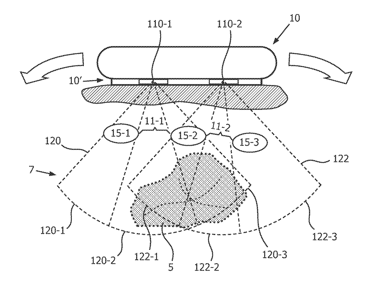
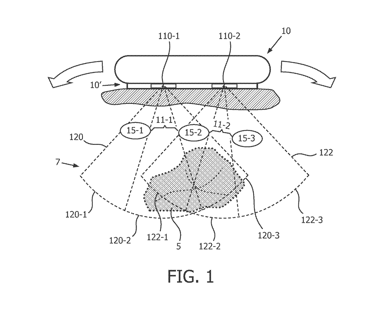
[0036]FIG. 1 illustrates intercostal gaps in an acoustic image aperture which might be produced by the presence of obstructions (e.g., ribs) disposed between an acoustic transducer and at least a portion of an imaging region.

[0037]In particular FIG. 1 illustrates an acoustic probe 10 (e.g., an ultrasound probe), including an acoustic transducer array 10′ for imaging an imaging region 7, which includes a region of interest (ROI) 5, for example a heart. Imaging region 7 also includes a plurality of obstructions 15-1, 15-2, 15-3, for example ribs, which are separated and spaced apart from each other by ...


PUM


Abstract

An apparatus and method of imaging an imaging region (7) employ an acoustic transducer array (10′) to produce image data for the imaging region (7), wherein there are one or more obstructions (15-1, 15-2, 15-3) between the acoustic transducer array (10′) and at least a portion (5) of the imaging region (7). One or more processors exploit redundancy in transmit/receive pair paths among the acoustic transducers in the acoustic transducer array (10′) to compensate for missing image data of the imaging region (7) due to the one or more obstructions (15-1, 15-2, 15-3), and produce an image of the imaging region (7) from the compensated image data.

Description

TECHNICAL FIELD[0001]This invention relates to acoustic imaging apparatuses, systems and methods.BACKGROUND AND SUMMARY[0002]In acoustic (e.g., ultrasound) imaging, or other active acoustics imaging, an array of transducers first transmits a pulse into the medium, usually with appropriate delay to generate a focused beam, and then receives the echo. Beamforming is used to reconstruct an image of the medium. The quality of the image is related to the point-spread function (PSF), or response of the imaging system to a single point. The PSF is related to the aperture of the array. In the far field approximation, the lateral profile of the PSF is the square of the Fourier transform of the aperture amplitude distribution. If no apodization is used it would be a sinc2 function.[0003]However part of the aperture may be blocked by one or several obstacles. In medical ultrasound, the obstacle could be a rib. For example, ultrasound imaging of the heart through the chest (transthoracic ultras...

Claims


Application Information

Patent Timeline
IPC IPC(8): G01S7/52A61B8/00A61B8/08G01S15/89
CPCG01S7/52047G01S15/8977A61B8/5269A61B8/4483G01S15/8997G01S15/8927G01S15/89G06T5/00G06T7/0012
Inventor ROBERT, JEAN-LUCRADULESCU, EMIL GEORGEVIGNON, FRANCOIS GUY GERARD MARIE
Owner KONINKLJIJKE PHILIPS NV
Why Eureka
Try Eureka