Cell area determination method, cell imaging system, and cell image processing apparatus

Active Publication Date: 2017-06-29
SYSMEX CORP +1
View PDF7 Cites 3 Cited by
  • Summary
  • Abstract
  • Description
  • Claims
  • Application Information

AI Technical Summary

Benefits of technology

[0007]When mechanically determining the characteristics of a cell, it is desirable to be as accurate as possible in differentiating non-cell regions such as background regions and the like from cell re

Problems solved by technology

However, since cells have no definite shape, and it is not always easy to recognize cells as cells in cell images by mechanical process.
In the case of transplant cells in particu

Method used


Image

  • Cell area determination method, cell imaging system, and cell image processing apparatus
  • Cell area determination method, cell imaging system, and cell image processing apparatus
  • Cell area determination method, cell imaging system, and cell image processing apparatus

Examples


Example

1. Cell Imaging System

[0028]1.1 Summary

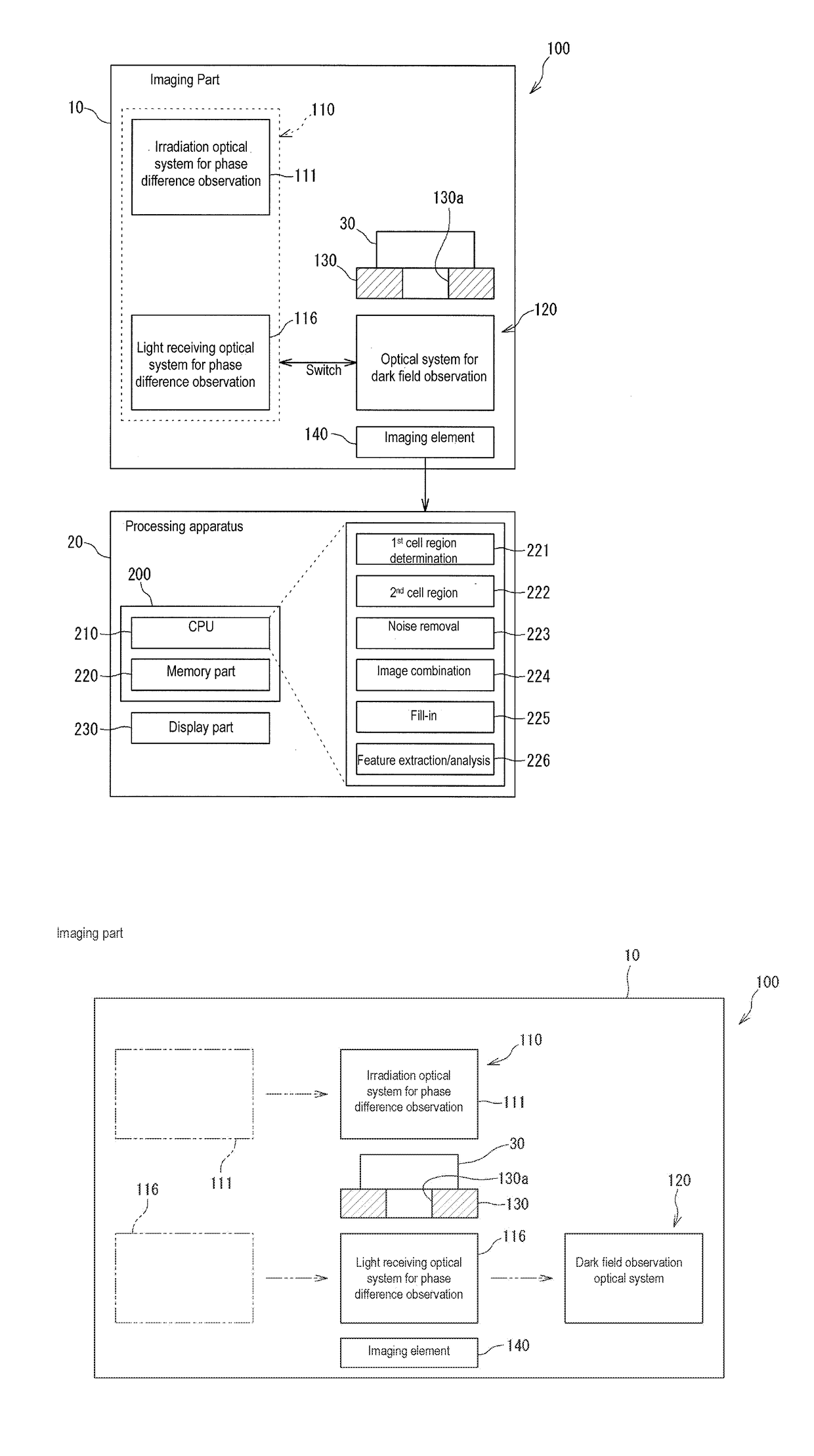
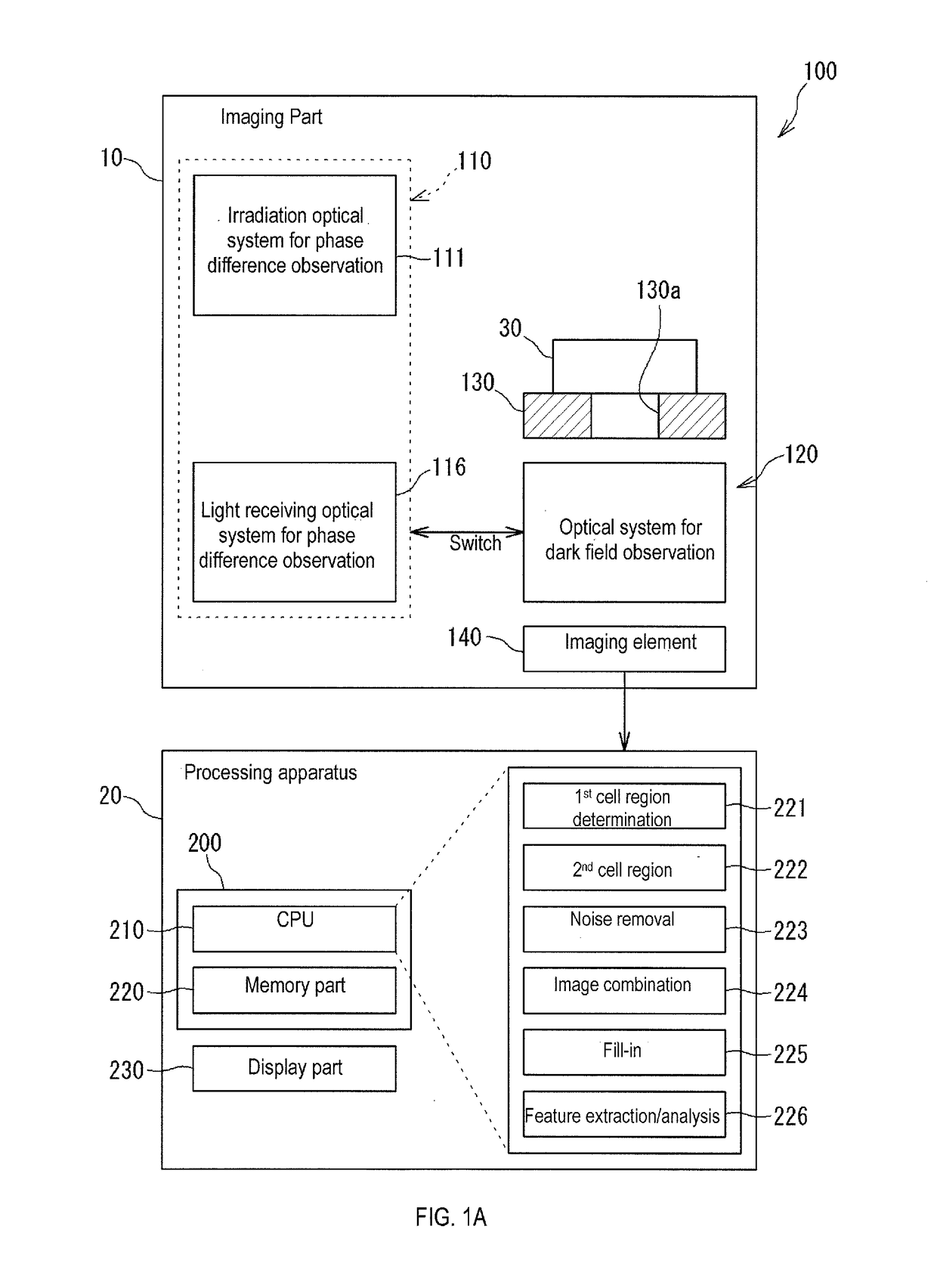
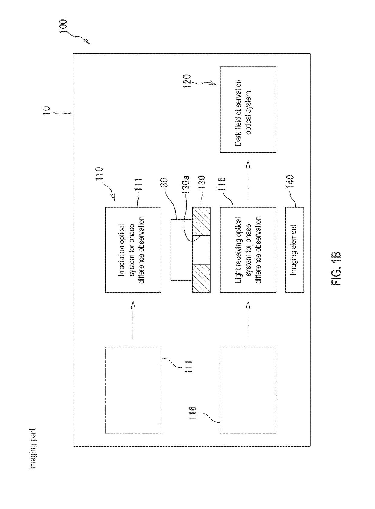
[0029]The cell imaging system 100 shown in FIG. 1A has an imaging part 10 and processing apparatus 20. The cell imaging system automatically recognizes cell regions in a cell image based on the cell image of the cell. The imaging part 10 images the cell and generates the cell image. The generated cell image is sent to the processing apparatus 20. The processing apparatus 20 processes the cell image.

[0030]The cell to be imaged is, for example, a transplantation cell for regenerative medicine. The transplantation cell is, for example, a cultured mesenchymal stem cell (MSC). For example, cells derived from human bone marrow (human bone marrow-derived mesenchymal stem cell) may be used as MSC. Morphological analysis of cultured MSCs is effective for evaluating the condition of MSCs, for example, evaluating transplantation suitability. Cell region determination in cell images is required for morphological analysis of cells.

[0031]The cells to be imag...


PUM


Abstract

A method comprises obtaining a first cell image of a cell by a first observation method, obtaining a second cell image of the cell by a second observation method that is different from the first observation method, and determining the region of the cell based on the first cell image and the second cell image.

Description

RELATED APPLICATIONS[0001]This application claims priority from prior Japanese Patent Application No. 2015-257131, filed on Dec. 28, 2015, entitled “CELL REGION DETERMINATION METHOD, CELL IMAGING SYSTEM, CELL IMAGE PROCESSING APPARATUS, AND COMPUTER PROGRAM,” the entire contents of which are incorporated herein by reference.BACKGROUND OF THE INVENTION[0002]1. Field of the Invention[0003]The invention relates to a cell region determination method, cell imaging system, cell image processing apparatus, and computer program.[0004]2. Description of the Related Art[0005]U.S. Pat. No. 7,711,174 discloses a method of determining structural characteristics of a cell by obtaining cell outline and cell texture information from a cell image of a culture process, and analyzing the obtained information.SUMMARY OF THE INVENTION[0006]The scope of the present invention is defined solely by the scope of the appended claims, and is not affected to any degree by the statements within this summary.[0007...

Claims


Application Information

Patent Timeline
IPC IPC(8): G06T7/13G06T7/136G06T7/00G06T7/194G06T7/90G06K9/00G06T7/174
CPCG06T7/13G06K9/0014G06T7/136G06T7/174G06T2207/30052G06T7/90G06T7/97G06K9/00127G06T2207/30024G06T7/194G06V20/693G06V20/695G06V10/145G06V10/25G06T5/50G06T2207/10056G06T2207/10152G06T2207/30221G06V20/69
Inventor HAKAMADA, KAZUMIAIHARA, YUKIOKADA, MASAYASATO, TOSHIYUKISEKIYA, ICHIROKOBAYASHI, EIJI
Owner SYSMEX CORP
Why Eureka
Try Eureka