
Power converter and switching power supply device

a power converter and switching power technology, applied in the direction of electric variable regulation, process and machine control, instruments, etc., can solve the problems of reducing the switching consumption of the step-down direct current power converter, unable to find a corresponding solution, and affecting the operation of the power converter. the effect of switching consumption and the reduction of the switching time of the circui

Active Publication Date: 2017-06-29
SHENZHEN SKYWORTH RGB ELECTRONICS CO LTD +1
View PDF11 Cites 12 Cited by
  • Summary
  • Abstract
  • Description
  • Claims
  • Application Information

AI Technical Summary

Benefits of technology

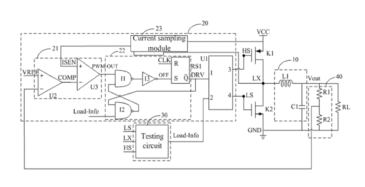
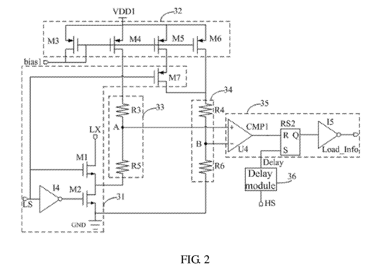
The present invention is aimed at reducing the switching consumption of a step-down direct current power converter while improving its load efficiency. The invention achieves this by connecting a main switch and an after flow switch in series between the power supply and the ground, and connecting an energy storing and outputting circuit to the connecting node of the main and after flow switches. A driving circuit changes the state of the main and after flow switches based on a preset clock frequency and a testing circuit. The testing circuit detects voltage at the connecting node and when the voltage is higher than zero, it triggers the driving circuit to shut down the after flow switch and allow the load to work normally through stored voltage. On the other hand, when the voltage level is too low to maintain the load's normal operation, the feedback circuit triggers the driving circuit to change from the shutting state to a conducting state, and the energy-storing device is recharged. This ensures that the after flow switch does not turn on immediately to supply power to the load, but instead the load is powered for a while through stored energy, reducing the shutting cycle of the main switch and the conducting times of the switches, resulting in reduced switching consumption of the circuit.

Problems solved by technology

However, every time the switching tube is conducting or shutting down, it consumes a certain amount of power, if the conducting times of the switching tube is reduced, and the load works as usual, so an aim of reducing the consumption of the circuit is realized, however, currently there is no corresponding method to solve the problem of the switching consumption of the step-down direct current power converter.

Method used


Image

  • Power converter and switching power supply device
  • Power converter and switching power supply device
  • Power converter and switching power supply device

Examples


Embodiment Construction

[0041]It is to be understood that, the described embodiments are only some exemplary embodiments of the present disclosure, and the present disclosure is not limited to such embodiments.

[0042]The present disclosure provides a power converter.

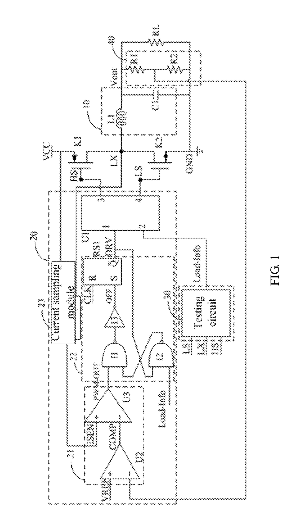
[0043]Referring to FIGS. 1-3, in an exemplary embodiment, the power converter includes a main switch K1 and an after flow switch K2 connected in series between a power supply VCC and a ground, an energy storing and outputting circuit 10 connected with a connecting node LX of the main switch K1 and the after flow switch K2, a driving circuit 20 changes connecting states of the main switch K1 and the after flow switch K2 according to a preset clock frequency, the energy storing and outputting circuit 10 stores energy for supplying a working voltage to a load RL, when the main switch K1 is conducting, a direct power source inputted by the power supply VCC is transmitted to the energy storing and outputting circuit 10, for controlling the energy sto...


PUM


Abstract

The present disclosure discloses a power converter and a switching power supply device. The power converter includes an energy storing and outputting circuit used for charging a load after storing energy, a main switch used for transmitting input power to the energy storing and outputting circuit when the main switch is conducting, an after flow switch used for supplying an after flow loop to the energy storing and outputting circuit when the main switch is shut down, a driving circuit used for changing connecting states of the main switch and the after flow switch according to a preset clock frequency, and a testing circuit and a feedback circuit, the testing circuit is used for testing a voltage on a connecting node of the main switch and the after flow switch.

Description

FIELD OF THE DISCLOSURE[0001]The present disclosure relates to the field of switching power technologies, and in particular, to a power converter and a switching power supply device.BACKGROUND OF THE DISCLOSURE[0002]Currently, step-down direct current power converter is widely used for the working frequency of the power converter's circuit is high, and the circuit is stably.[0003]The traditional step-down direct current power converter normally adopts a pulse width modulation mode to drive, so, no matter the step-down direct current power converter is in a overloading mode, or a light loading mode, an outputting inductor is always working at a current continuous mode (CCM), that is, a current of the inductor is always larger than zero. In the current continuous mode, a conducting cycle (frequency) of a switching tube does not change, and equals to a clock frequency, the power converter merely adjusts outputting to adjust outputting power of the circuit.[0004]However, every time the ...

Claims


Application Information

Patent Timeline
IPC IPC(8): H02M3/158H02M1/08
CPCH02M3/158H02M2001/0009H02M1/08H02M3/1588Y02B70/10H02M1/0019H02M1/0054H02M1/0009
Inventor ZUO, SHIJUNCHEN, LUTENG, MOUYAN
Owner SHENZHEN SKYWORTH RGB ELECTRONICS CO LTD
Learn More