
Centrosymmetric radio frequency electrode configuration for skin treatment

a radio frequency electrode and configuration technology, applied in the field of skin treatment devices, can solve the problems of low conductance, high electrical resistance, direct influence of tissue impedance on the extent of heating, etc., and achieve the effect of generating non-ablative fractional skin lesions and improving safety

Pending Publication Date: 2017-07-06
KONINKLJIJKE PHILIPS NV
View PDF19 Cites 8 Cited by
  • Summary
  • Abstract
  • Description
  • Claims
  • Application Information

AI Technical Summary

Benefits of technology

The invention proposes a device with a specific electrode design that allows for effective skin rejuvenation with minimal discomfort to the patient. The device has an inner electrode with a cross-sectional dimension of 200-500 μm, which, when combined with a low treatment voltage of below 50 Volts, generates large thermal lesions. The device also has a ratio between the skin contact surface of the outer electrode and the inner electrode that is greater than 2, which helps to prevent unnecessary heating of the skin. Essentially, this invention provides a device that can safely and efficiently improve skin appearance while minimizing patient discomfort.

Problems solved by technology

Tissue impedance directly affects the extent of the heating: RF propagates more easily through tissues with high conductivity (low electrical resistance), while tissues with high electrical resistance (high impedance, low conductance) are poor conductors of RF energy.
To date, fractional skin treatments using RF are limited to professional use.
This is particularly challenging since the amount of RF energy deposited in the tissue depends on local tissue impedance, and skin tissues have inhomogeneous impedance distribution.
This uncertainty in impedance combined with the use of high current densities and voltages results in uncertainty in achieved temperatures in skin tissues during treatment, resulting in the occurrence of both non-ablative thermal lesions and the undesirable ablative tissue damages.

Method used


Image

  • Centrosymmetric radio frequency electrode configuration for skin treatment
  • Centrosymmetric radio frequency electrode configuration for skin treatment
  • Centrosymmetric radio frequency electrode configuration for skin treatment

Examples


Embodiment Construction

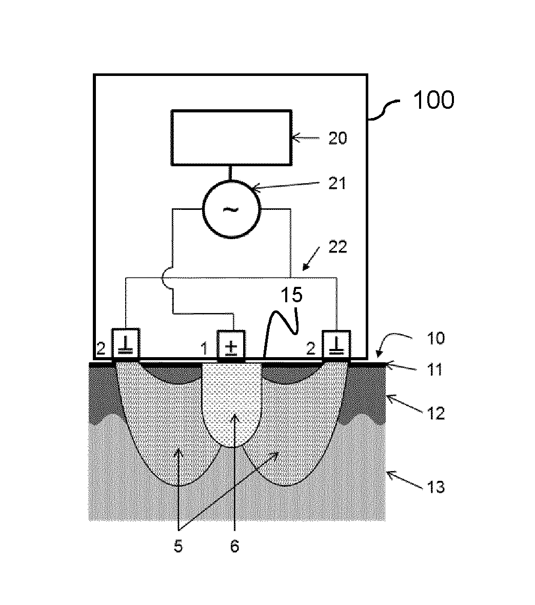
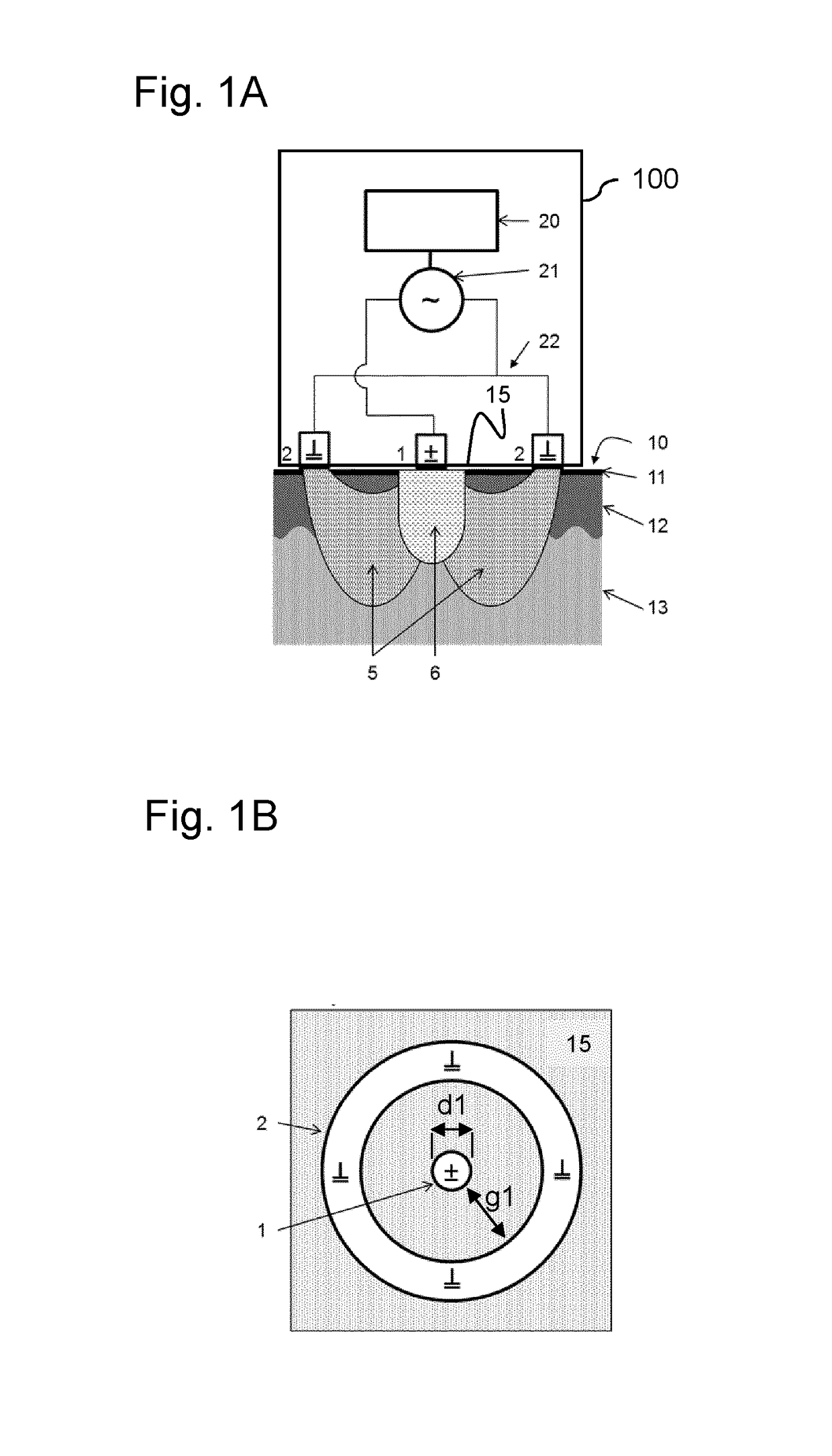
[0025]FIG. 1A is a schematic cross section of a device 100 for skin treatment according to an embodiment of the present invention. In this exemplary embodiment, the device 100 comprises an inner electrode 1 and an annular (ring-shaped) outer electrode 2 surrounding the inner electrode 1. The device 100 also comprises an electronic controller 20, and a radio frequency (RF) generator 21 connected by wiring 22 to the electrodes 1 and 2. In this Figure, the electrodes 1, 2 are shown in a position on a skin surface 10 consisting of the stratum corneum 11, epidermis 12 and dermis 13. When powered, the electrodes 1, 2 create electric field lines 5 within the skin and, due to the applied voltage in combination with the skin impedance, heat is deposited within the skin, thereby creating a non-ablative lesion 6, when the local skin temperature reaches a level above 65° C. and stays under 100° C. The electronic controller 20 may be arranged to control the RF generator 21. The RF generator 21 w...


PUM


Abstract

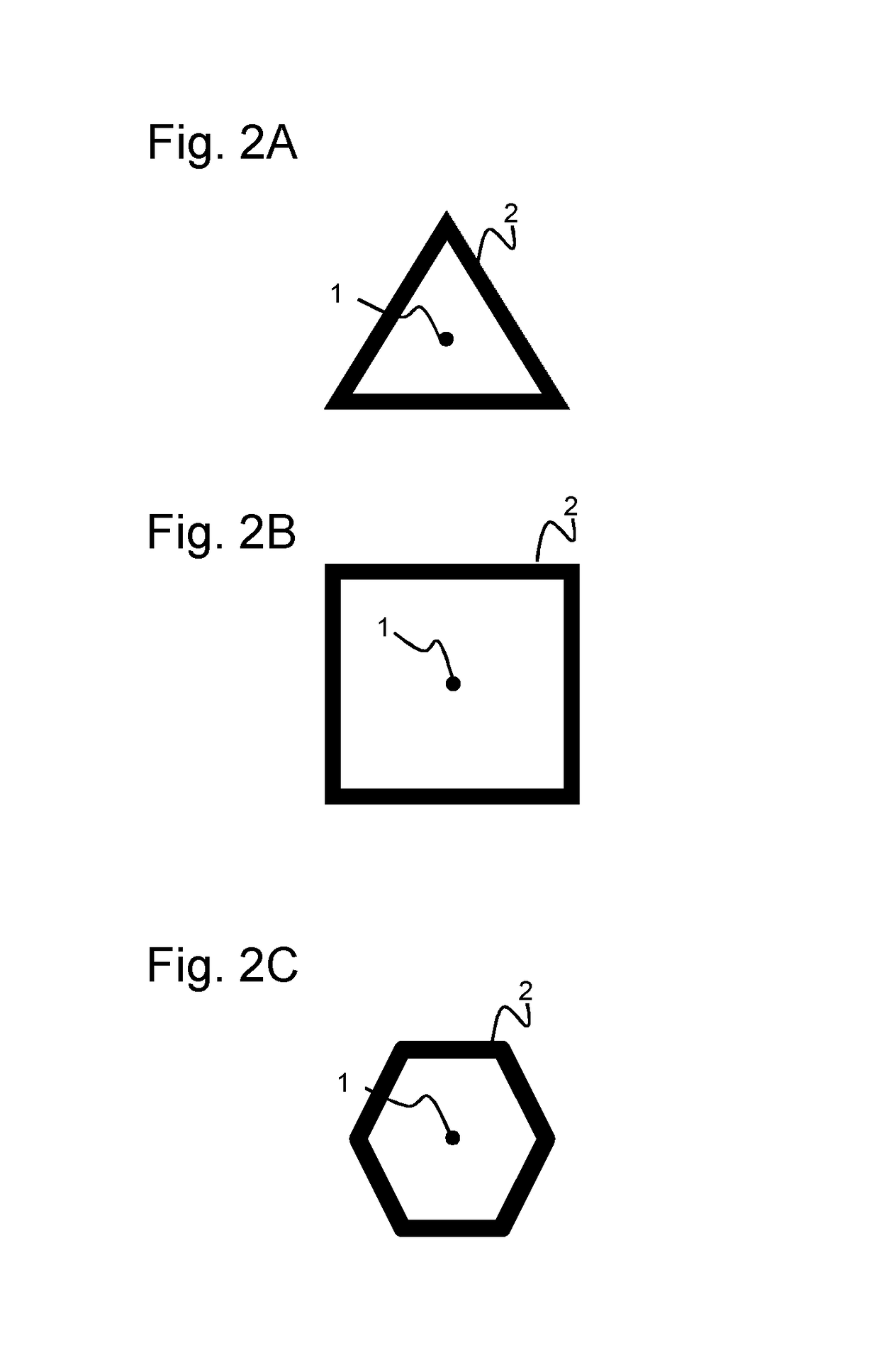
The invention relates to a device (100) for RF skin treatment comprising an outer electrode (2) arranged on an operational side (15) of the device. The outer electrode has an annular or equilateral polygonal shape. An inner electrode (1) is arranged at a center of the outer electrode and is surrounded by the outer electrode. An RF generator (21) is arranged to supply an RF treatment voltage between the inner electrode (1) and the outer electrode (2). A skin contact surface of the inner electrode has a largest cross-sectional dimension in a range of 200-500 μm, and the RF treatment voltage is less than 50 V. The invention provides a device with improved safety in that it enables the creation of non-ablative fractionated skin lesions, particularly using a relatively low RF treatment voltage for treating the skin as compared to known devices and without the necessity of a feedback or monitoring system.

Description

FIELD OF THE INVENTION[0001]The invention relates a device for skin treatment, in particular for radio frequency (RF) treatment of human skin. The device is primarily suitable for skin tightening and / or skin rejuvenation, in particular for fractional RF skin treatment. The invention also relates to the use of such a device for skin treatment.BACKGROUND OF THE INVENTION[0002]Radio frequency (RF) is conventionally used in both the professional and home-use aesthetic market for skin tightening. The ability to heat a large volume at dermal skin level has made the radio frequency technology the standard for skin tightening and for treating skin laxity. Compared to laser treatments, RF devices have a relatively lower cost price and can provide larger-volume and deeper tissue contraction. Additionally, RF energy dissipation does not rely on absorption of light by chromophores, so that tissue pigmentation or the vascular network does not interfere with the delivery of energy.[0003]The basic...

Claims


Application Information

Patent Timeline
IPC IPC(8): A61N1/00A61B18/14A61N1/04A61N1/40A61N1/32A61N1/18
CPCA61N1/00A61N1/328A61N1/18A61B2018/0047A61N1/403A61B18/14A61N1/0476
Inventor JURNA, MARTINPALERO, JONATHAN ALAMBRABARAGONA, MARCOHORTON, MARGARET RUTHVARGHESE, BABU
Owner KONINKLJIJKE PHILIPS NV
Learn More