Aircraft engine and associated method for driving the fan with the low pressure shaft during taxi operations

a fan and low pressure technology, applied in the direction of machines/engines, mechanical equipment, transportation and packaging, etc., can solve the problems of increasing affecting the efficiency of taxi operations, so as to avoid any increase in the cost of aircraft, avoid any increase in the weight and fuel consumption of aircraft, and avoid some brake wear and fuel consumption

Active Publication Date: 2017-07-06
THE BOEING CO
View PDF12 Cites 22 Cited by
  • Summary
  • Abstract
  • Description
  • Claims
  • Application Information

AI Technical Summary

Benefits of technology

[0004]An aircraft engine, an electric taxi system and a corresponding method are provided in accordance with an example embodiment in order to provide the motive force for the aircraft during taxi operations. By utilizing the electric taxi system, a pilot may operate the aircraft during taxi operations utilizing the same controls as are utilized during flight. Additionally, the aircraft need not include an additional system for providing the motive force during taxi operations, thereby avoiding any increase in the cost of the aircraft, while correspondingly avoiding any increase in the weight and fuel consumption of the aircraft. The aircraft engine, the electric taxi system and the corresponding method of an example embodiment of the present disclosure are configured to drive the fan assembly of the aircraft engine with energy provided by an energy storage device of the electric taxi system such that the speed of the aircraft is appropriate for taxi operations, thereby permitting the core gas turbine engine of the aircraft engine to be shut off during taxi operations and avoiding some brake wear and fuel consumption.

Problems solved by technology

However, the idle speed of some modern aircraft engines causes the fan to be rotated at a speed that is sufficiently high so as to cause the aircraft to travel too quickly for at least some taxi operations.
Having to regularly utilize the brakes to control the speed of the aircraft during taxi operations increases the brake wear and leads to less productive use being made of the fuel consumed during taxi operations.
However, a separate drive system to provide the motive force during taxi operations may increase the cost of the aircraft as well as the weight and corresponding fuel consumption of the aircraft.
Moreover, an additional drive system dedicated to providing the motive force for the aircraft during taxi operations may include an additional set of controls that a pilot must operate in order to drive the aircraft during taxi operations, thereby adding to the complexity of the cockpit and the training requirements for a pilot.

Method used


Image

  • Aircraft engine and associated method for driving the fan with the low pressure shaft during taxi operations
  • Aircraft engine and associated method for driving the fan with the low pressure shaft during taxi operations
  • Aircraft engine and associated method for driving the fan with the low pressure shaft during taxi operations

Examples


Embodiment Construction

[0016]Embodiments of the present disclosure now will be described more fully hereinafter with reference to the accompanying drawings, in which some, but not all embodiments are shown. Indeed, these embodiments may be embodied in many different forms and should not be construed as limited to the embodiments set forth herein; rather, these embodiments are provided so that this disclosure will satisfy applicable legal requirements. Like numbers refer to like elements throughout.

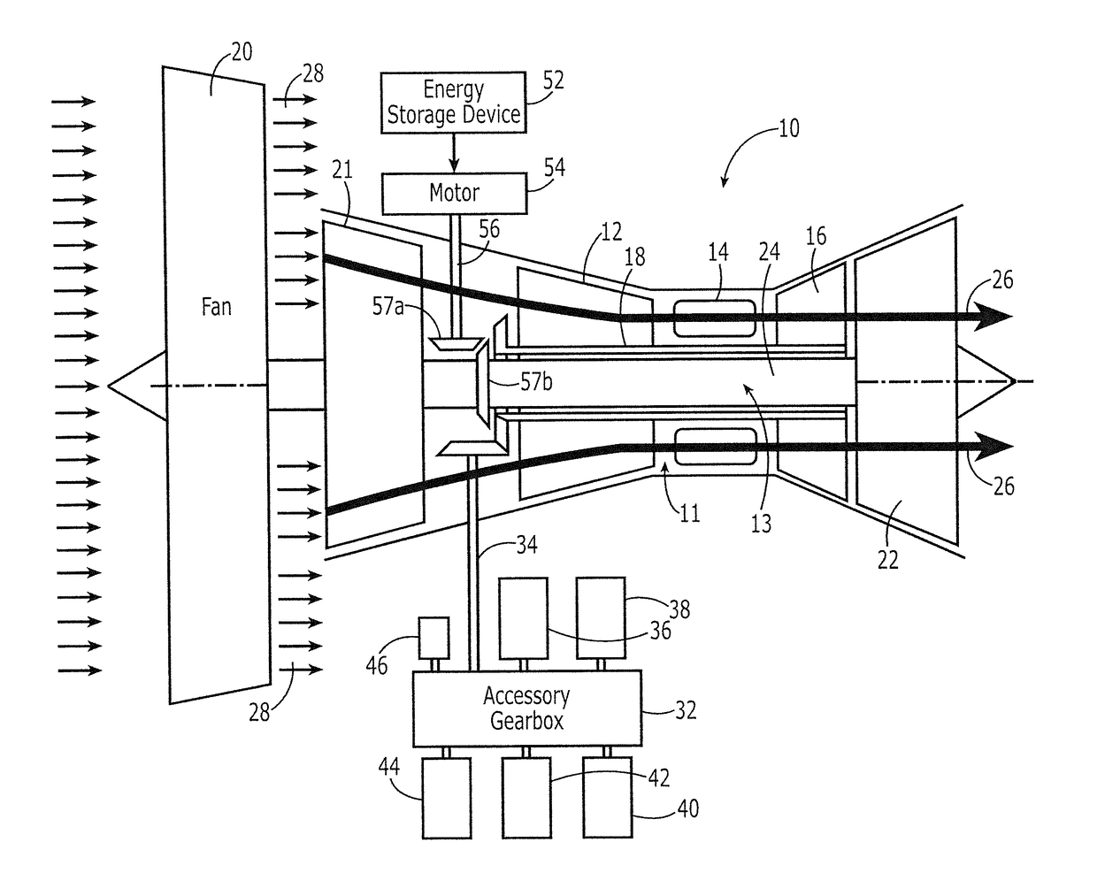
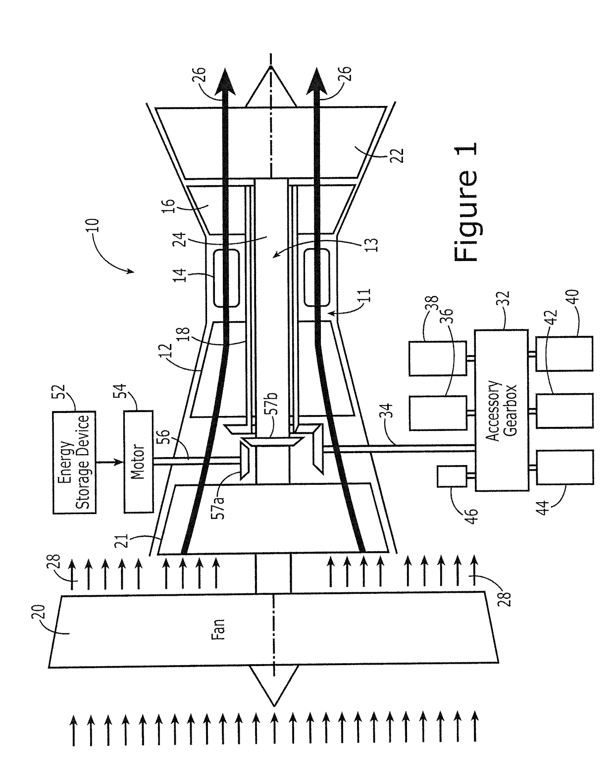
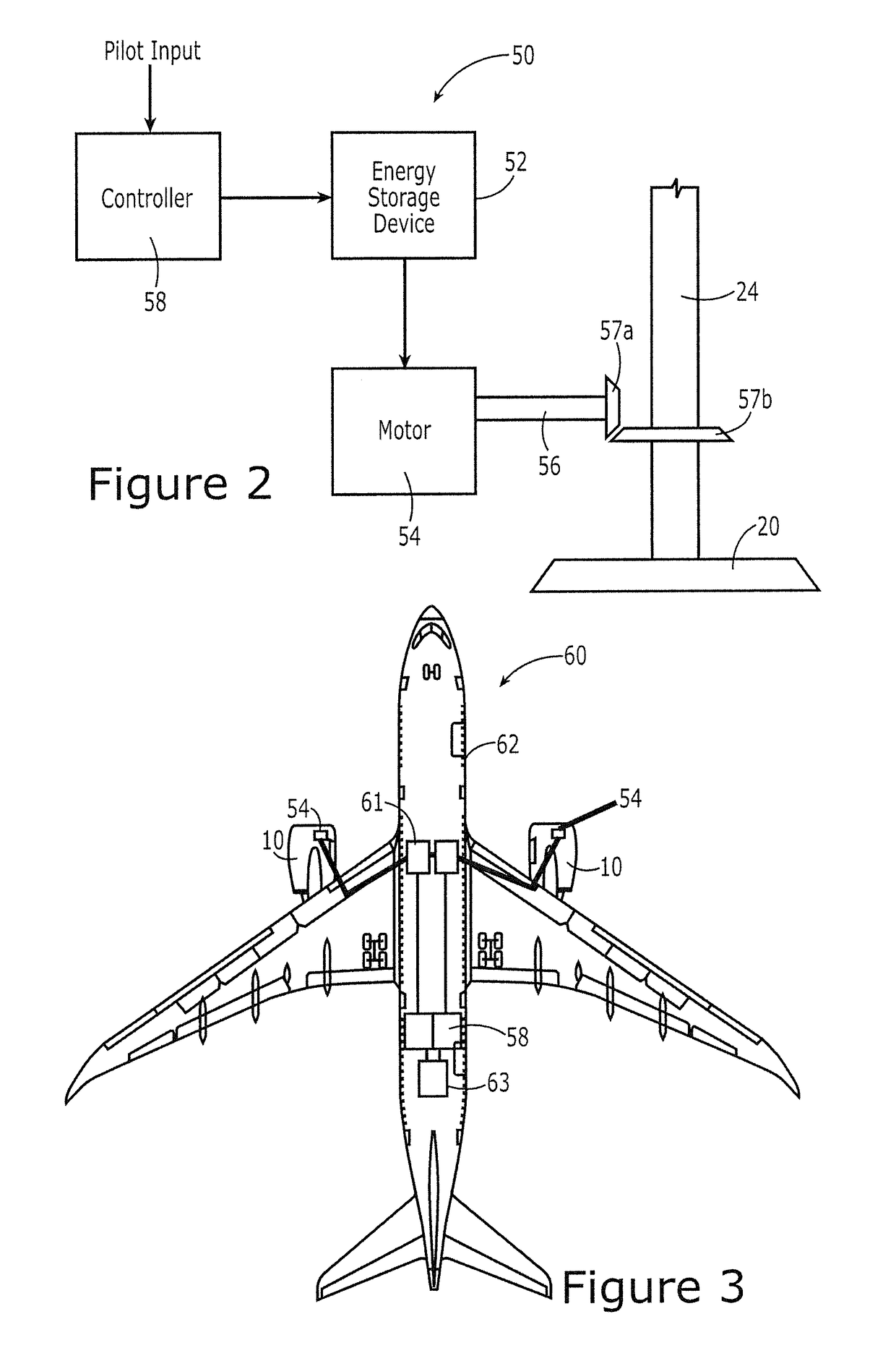
[0017]An aircraft engine, an electric taxi system and an associated method are provided in order to controllably drive the fan assembly of an aircraft engine with the electric taxi system in order to provide the motive force required by the aircraft during taxi operations. As shown in FIG. 1, an aircraft engine 10, such as a turbofan, includes a core gas turbine engine 11 and a fan assembly 13. The core gas turbine engine 11 may be referenced as the high pressure spool and includes a compressor 12, a combustor 1...


PUM


Abstract

An aircraft engine, an electric taxi system and a corresponding method are provided to facilitate taxiing without operation of the core gas turbine engine by driving the fan assembly with the electric taxi system during taxi operations. An aircraft engine is provided that includes a core gas turbine engine including a compressor, a combustor and a high pressure turbine. The aircraft engine also includes a fan assembly coupled to the core gas turbine engine. The aircraft engine further includes an electric taxi system coupled to the fan assembly. The electric taxi system includes an energy storage device and a motor responsive to energy provided by the energy storage device. The motor is coupled to the fan assembly and is configured to drive the fan assembly during taxi operations.

Description

TECHNOLOGICAL FIELD[0001]An example embodiment relates generally to a technique for driving the fan during taxi operations and, more particularly, to driving the fan with the low pressure shaft during taxi operations.BACKGROUND[0002]In order to taxi, an aircraft operates its engines at idle speed with occasional increases in engine speed to start motion or speed up taxi. Nearly all of the engine thrust is created by the engine fan which is driven by the engine core exhaust running through a turbine coupled via a shaft to the fan. However, the idle speed of some modern aircraft engines causes the fan to be rotated at a speed that is sufficiently high so as to cause the aircraft to travel too quickly for at least some taxi operations. Thus, pilots may be forced to routinely apply the brakes concurrent with the operation of the engines at idle speed in order to appropriately control the speed of the aircraft during taxi operations. Having to regularly utilize the brakes to control the ...

Claims


Application Information

Patent Timeline
Patent Type & Authority Applications(United States)
IPC IPC(8): B64D41/00B64D27/10
CPCB64D27/10B64D41/00B64D27/12F02C6/04F02C7/36F02K3/06B64D27/00B64D33/00B64D35/00F01D15/10F01D25/36F05D2220/36Y02T50/80B64D27/18
Inventor MACKIN, STEVE G.
Owner THE BOEING CO
Why Eureka
Try Eureka