
Surface modification treatment agent, member for image forming apparatus and toner fixing mechanism

Inactive Publication Date: 2017-07-06
NOK CORP +1
View PDF5 Cites 0 Cited by
  • Summary
  • Abstract
  • Description
  • Claims
  • Application Information

AI Technical Summary

Benefits of technology

The present invention is about a treatment agent that can make surfaces less sticky and smoother. It can be used for members of image forming apparatus and toner fixing mechanisms.

Problems solved by technology

Unfortunately, this conventional method requires a larger size of the heater itself.
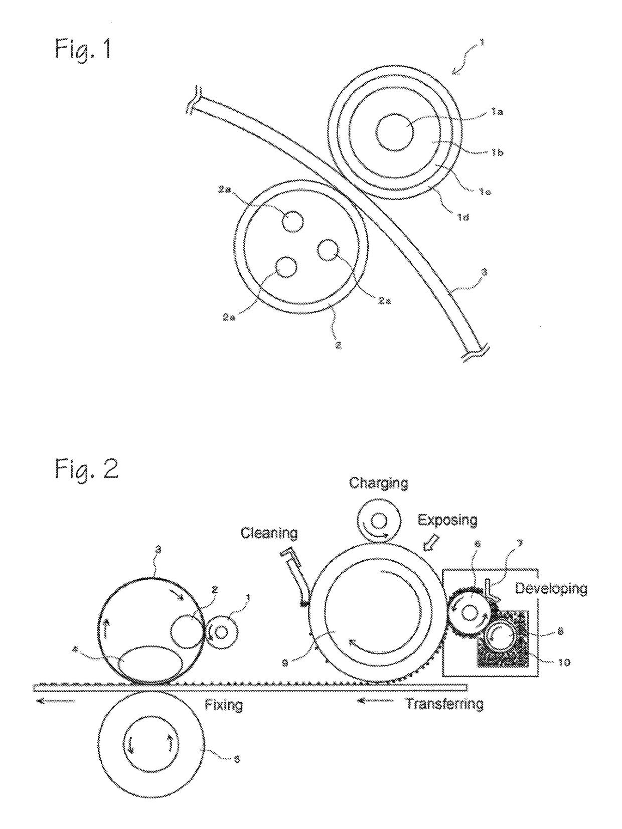
The above structure allows for a smaller heating mechanism of a fixing belt, resulting in reduced power for heating and elevated heating rates.
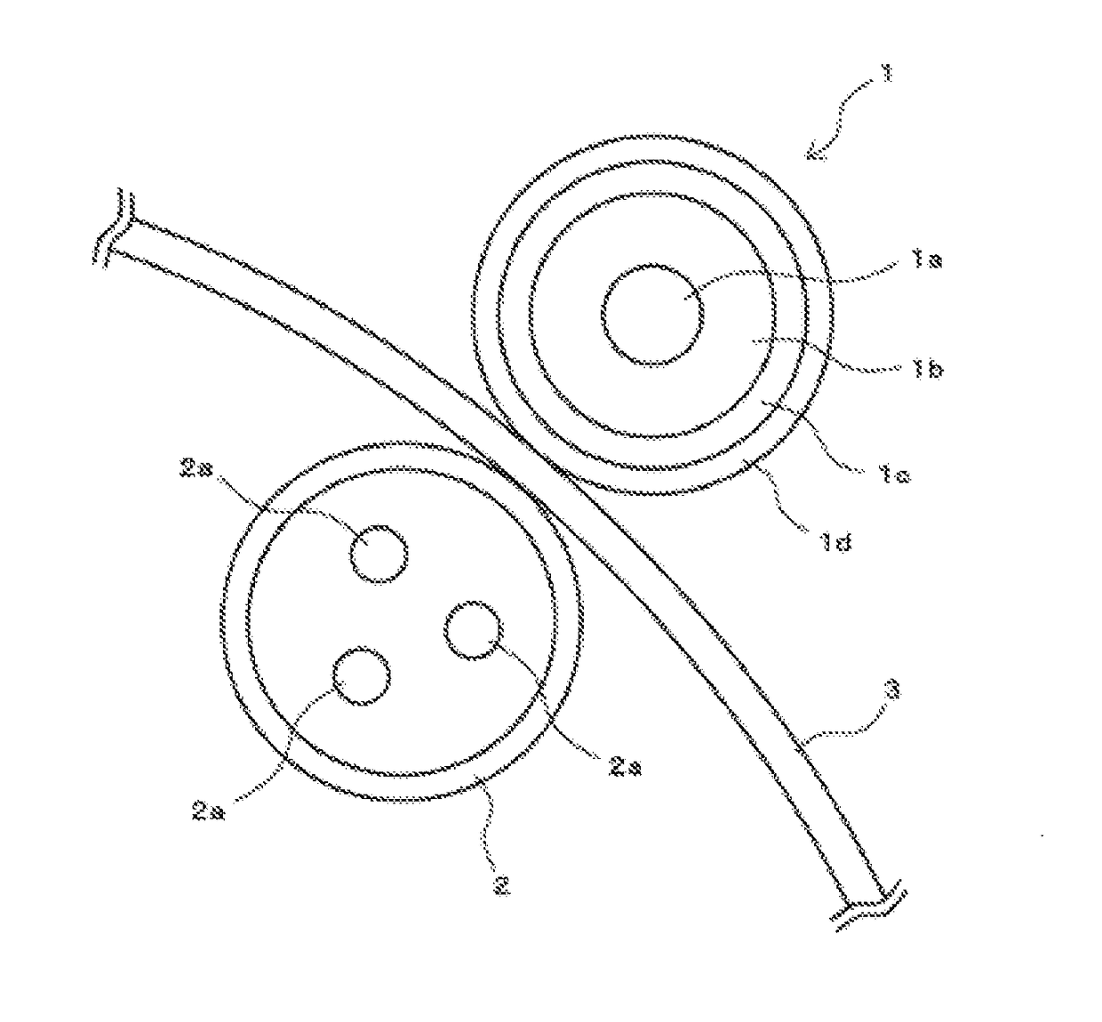
Despite these advantages, the structure is prone to accumulation of a residual toner on a pressing roller after the toner moves from the surface of a fixing belt.
However, such a development roller unfortunately causes higher coefficient of dynamic friction, and fails to achieve lower tackiness and lower friction.
However, this method has several drawbacks: falling of PTFE particles; generation of irregularities; and decreased adhesion with a base material.
These substances, once adhered, cannot be totally removed.
In fact, this method makes it difficult to determine the coefficient of friction under a predetermined value, resulting in insufficient non-tackiness.
Similarly, the above disadvantage is found for a silicone resin coating.
A method for adding oil for surface lubrication and lower friction is employed, but this method is prone to degraded adhesion with a base material, transfer of oil bleeding on the surface to the counterpart surface, removal of oil by brushing, and loss of lubrication by a reciprocating motion.

Method used


Image

  • Surface modification treatment agent, member for image forming apparatus and toner fixing mechanism
  • Surface modification treatment agent, member for image forming apparatus and toner fixing mechanism
  • Surface modification treatment agent, member for image forming apparatus and toner fixing mechanism

Examples


example 1

[0116]

alkoxyoligomer (amount of alkoxy group: 24 wt %) (″X-40-9225,″ Product from Shin-Etsu Chemical Co.,Ltd.) . . . 100 parts by weighttitanium catalyst (″D-20,″ Product from Shin-EtsuChemical Co., Ltd.) . . . 2.0 parts by weightOH-modified silicone oil (″X-22-160AS,″ Product from Shin-Etsu Chemical Co., Ltd.) . . . 4.2 parts by weightdiluent solvent; methyl ethyl ketone . . . 50 parts by weight

[0117]The above components were mixed to prepare a surface modification treatment agent.

[0118]

[0119]A silicone rubber base material layer was formed around a core material, and then a Ni electroforming laminated body was formed, and a surface modification treatment agent was spray-coated on the Ni electroforming surface to calcine the same 10 minutes after air drying. The thickness of a surface-modified covering layer was 2 to 3 μm.

[0120]

[0121]Similarly, a SUS301 steel plate 0.2 mm thick was spray-coated and calcined to prepare a test piece of metal laminate.

[0122]

[0123]The above test piece ...

example 2

[0138]The test conditions were the same as the Example 1, except that an OH-modified silicone oil was replaced with a dimethyl silicone oil (“KF-96-50CS,” Product from Shin-Etsu Chemical Co., Ltd.: viscosity; 50 cSt) in the Example 1 to obtain a surface modification treatment agent.

example 3

[0139]The test conditions were the same as the Example 1, except that an OH-modified silicone oil was replaced with a dimethyl silicone oil (“KF-96-10,000CS,” Product from Shin-Etsu Chemical Co., Ltd.: viscosity; 10,000 cSt) in the Example 1 to obtain a surface modification treatment agent.


PUM

PropertyMeasurementUnit
Kinematic viscosityaaaaaaaaaa
Frictionaaaaaaaaaa

Abstract

An object of the present invention is to provide a surface modification treatment agent capable of achieving lower tackiness and lower friction, a member for an image forming apparatus and a toner fixing mechanism. The object can be fulfilled by a surface modification treatment agent including: (A) an alkoxyoligomer; (B) (1) a long-chain silicone oil whose viscosity is within the range of 50 cSt to 500,000 cSt, or (2) at least one type of silicone oil selected from a carbinol-modified silicone oil, a carboxyl-modified silicone oil, a polyether-modified silicone oil, and a fluoroalkyl-modified silicone oil, whose one or both terminals and / or a side chain include a functional organic group introduced; and (C) an organotitanium compound or an organoaluminum compound; a member for an image forming apparatus, the surface of the member being modified with the above surface modification treatment agent; and a toner fixing mechanism including: a pressing roller 1 corresponding to the member for an image forming apparatus; a fixing belt 3; and a heating roller 2, in which the pressing roller 1 is disposed so as to be brought into contact with the heating roller 2 through the fixing belt 3.

Description

TECHNICAL FIELD[0001]The present invention relates to a surface modification treatment agent, a member for an image forming apparatus and a toner fixing mechanism, and particularly a surface modification treatment agent capable of achieving lower tackiness and lower friction, a member for an image forming apparatus and a toner fixing mechanism.BACKGROUND[0002]One recent type of developing device includes a non-magnetic one-component developing system. In the process of development, the system is known to be a contact developing system. This developing system allows a developing roll with a toner (developer) adhered thereon to uniformly contact with pressure on a photoreceptor.[0003]Generally, electrostatic latent image means forms electrostatic latent images on the surface of a photoconductive drum based on predetermined image information. On the other hand, a toner supply roller provides a toner to the surface of a developing roll. Subsequently, a member for regulating the amount o...

Claims


Application Information

Patent Timeline
IPC IPC(8): B32B9/04C09D183/06G03G15/20C09D7/65
CPCG03G15/2089C09D183/06G03G15/00G03G15/20B82Y30/00C09D5/00C09D5/006C08K7/24G03G15/206G03G2215/2035B82Y40/00C09D7/65C09D183/04C08L83/00C08K5/0091C09D7/40
Inventor HIGASHIRA, TOSHIHIROIKEDA, ATSUSHI
Owner NOK CORP
Learn More