
Emergency starting device and emergency starting method

a technology of emergency starting and emergency starting, which is applied in the direction of engine starters, machines/engines, transportation and packaging, etc., can solve the problems of not being able to provide a current high enough to start the engine, the accumulation of batteries during high rate discharging, and the engine cannot be started normally

Active Publication Date: 2017-07-06
ZHANG LEI
View PDF9 Cites 16 Cited by
  • Summary
  • Abstract
  • Description
  • Claims
  • Application Information

AI Technical Summary

Benefits of technology

The invention is a device called a super-capacitor, which can store and release energy quickly. It can handle high currents and is not affected by short circuits. It has a long lifespan without maintenance. The invention uses the super-capacitor to start an engine in emergency situations by using an accumulator battery and controlling the super-capacitor. It also uses a DC-DC booster circuit or a chargeable battery to charge the super-capacitor when needed. The technical effects of the invention are improved starting performance and reliability in emergency situations and longer lifespan of the energy-storage device.

Problems solved by technology

While the performance of the accumulator battery during high rate discharging or in a cold environment is so poor that it may not able to provide a current high enough to start the engine.
In addition, due to the performance degradation, the accumulator battery outputs a drastic changing voltage which may power down the starting system and thus the engine can not be started normally.
But the existing emergency devices are usually bulk and heavy, and the batteries in them are same with the accumulator battery used in the automobile, which has only 2-3 years's lifetime.
They don't function well in cold environment or with insufficient voltage, thus scheduled maintenance is needed to keep them effective.

Method used


Image

  • Emergency starting device and emergency starting method
  • Emergency starting device and emergency starting method
  • Emergency starting device and emergency starting method

Examples


Embodiment Construction

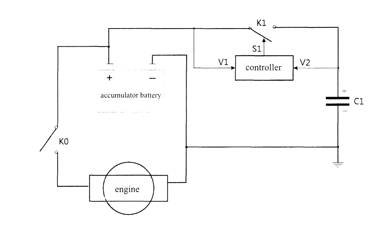
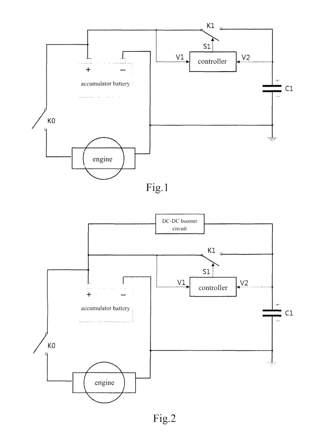
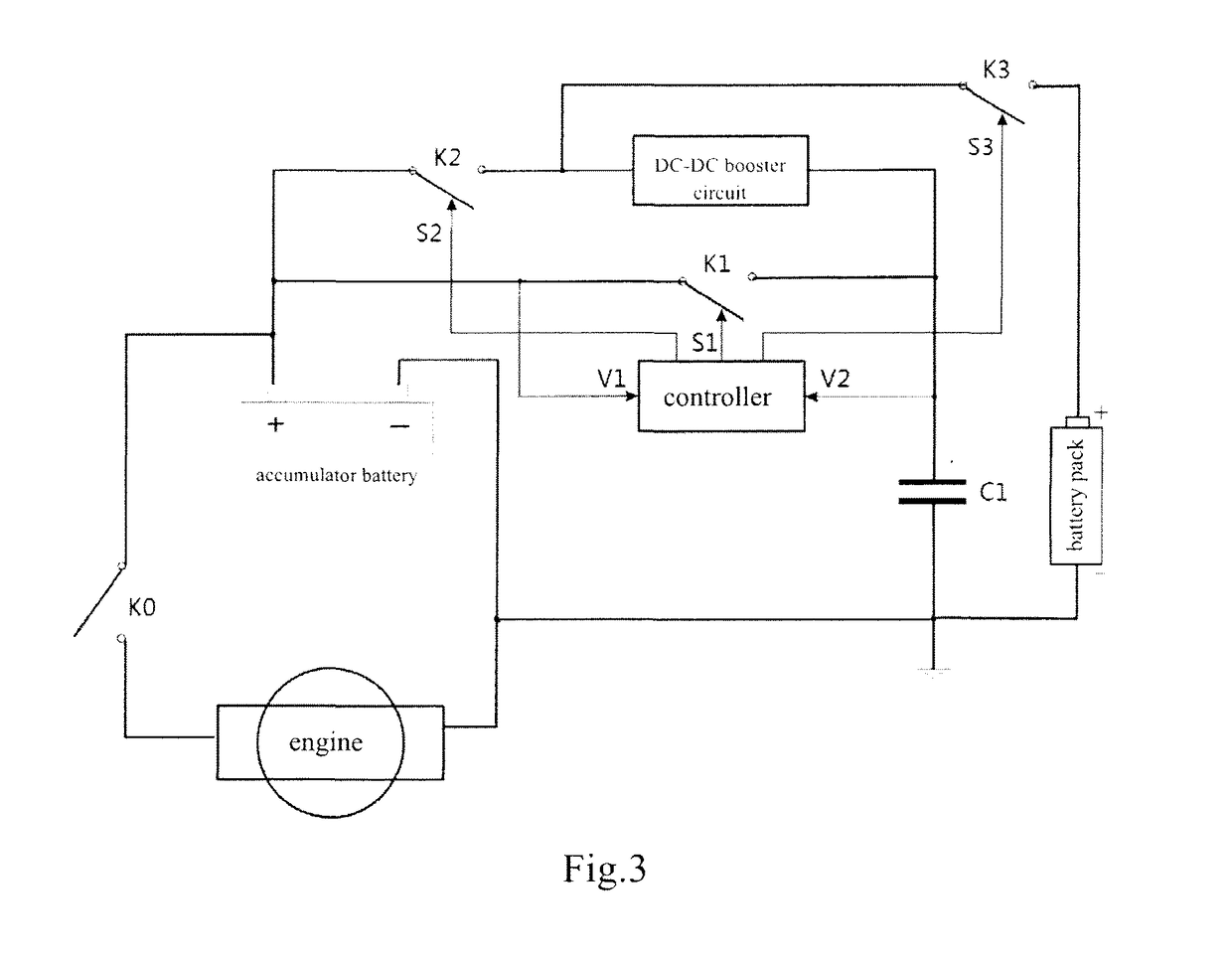
[0058]The starting system in the following embodiments of the invention is a starting system for gasoline engine, whose starting voltage is generally of 12V and the output voltage of the accumulator battery in it should be of 13-15V. When the output voltage of the accumulator battery cannot meet the requirement due to the weather or the shortage of energy (or power) caused by energy loss, i.e. in emergency circumstances, the emergency starting device of the invention can be connected to the starting system and substitute the starting system, which is not able to start the engine normally, to start the engine.

[0059]As shown in FIG. 1, in a first preferred embodiment of the invention, the emergency starting device of the invention has a first output end and a second output end, which are connected to the positive electrode and the negative electrode of the accumulator battery in the starting system respectively. The negative electrode of the accumulator battery is grounded.

[0060]The e...


PUM


Abstract

The present invention provides an emergency starting device, including a first output end and a second output end, wherein the first output end is used for being connected to a positive electrode of an accumulator battery in an engine starting system and the second output end is used for being connected to a negative electrode of the accumulator battery; the device includes a super-capacitor, a controller and a DC-DC booster circuit, wherein the controller receives first electrical signal from the accumulator battery and electrically connects the super-capacitor and the accumulator battery to start the engine with energy stored in the super-capacitor when the first electrical signal changes suddenly, the DC-DC booster circuit increases the output voltage of the accumulator battery to charge the super-capacitor. The invention further provides an emergency starting method accordingly. By using the super-capacitor, the controller and the DC-DC booster circuit the invention fits in various severe environments and can start an engine in emergency permanently and effectively.

Description

FIELD OF THE INVENTION[0001]The present invention relates to emergency starting technique for an engine, and more particularly, to an emergency starting device and an emergency starting method.DESCRIPTION OF THE PRIOR ART[0002]Starting system is used for starting an engine which can be a gasoline engine or a diesel engine. That is to say, it makes an idle engine work. Nowadays, almost all automobile engines and some small-sized farm machinery engines use electrical starting system, wherein accumulator battery is a critical component.[0003]To start an engine, the accumulator battery should provide a high starting current, which is generally in the range of 200-800 Amp. While the performance of the accumulator battery during high rate discharging or in a cold environment is so poor that it may not able to provide a current high enough to start the engine. In addition, due to the performance degradation, the accumulator battery outputs a drastic changing voltage which may power down th...

Claims


Application Information

Patent Timeline
Patent Type & Authority Applications(United States)
IPC IPC(8): F02N11/14H02J7/34H02J7/00
CPCF02N11/14H02J7/0054H02J7/345F02N11/0866F02N11/087F02N11/12F02N2011/0885F02N2011/0888F02N2200/043F02N2200/046H02J7/342
Inventor ZHANG, LEI
Owner ZHANG LEI
Learn More