
Scale trapping unit and water heater

a technology of scale trapping and water heater, which is applied in the direction of domestic hot water supply system, water softening, heating types, etc., can solve the problems of reducing heat transfer performance, flow path blockage, and effective heat transfer surface area, and achieves high scale trapping performance, high performance, and maintenance free

Active Publication Date: 2019-02-05
MITSUBISHI ELECTRIC CORP
View PDF8 Cites 0 Cited by
  • Summary
  • Abstract
  • Description
  • Claims
  • Application Information

AI Technical Summary

Benefits of technology

The present invention is a scale trapping unit that prevents the buildup of scale and pressure drop in a water heater system. This unit maintains high performance while trapping scale, and it is designed to operate efficiently for extended periods of time without the need for maintenance. The use of this scale trapping unit results in improved performance and reliability of the water heater system.

Problems solved by technology

A very important issue for the heat exchanger in a heat pump water heater is to keep the heat transfer surface clean consistently to transfer heat to water.
Contamination on the wall surface of the heat transfer surface reduces the effective heat transfer surface area, resulting in decreased heat transfer performance.
Further, accumulation of contaminants increases pressure drop that occurs with the water flow into the heat exchanger, and in the worst case, can cause flow path blockage.
One problem encountered particularly in districts where a concentration of hardness components in water (such as calcium ions, magnesium ions, ionic silica, and molecular silica) is high is that a less soluble inorganic compound salt called scales (scale particles) precipitates as a result of heating and deposits in the heat exchanger.

Method used


Image

  • Scale trapping unit and water heater
  • Scale trapping unit and water heater
  • Scale trapping unit and water heater

Examples


embodiment 1

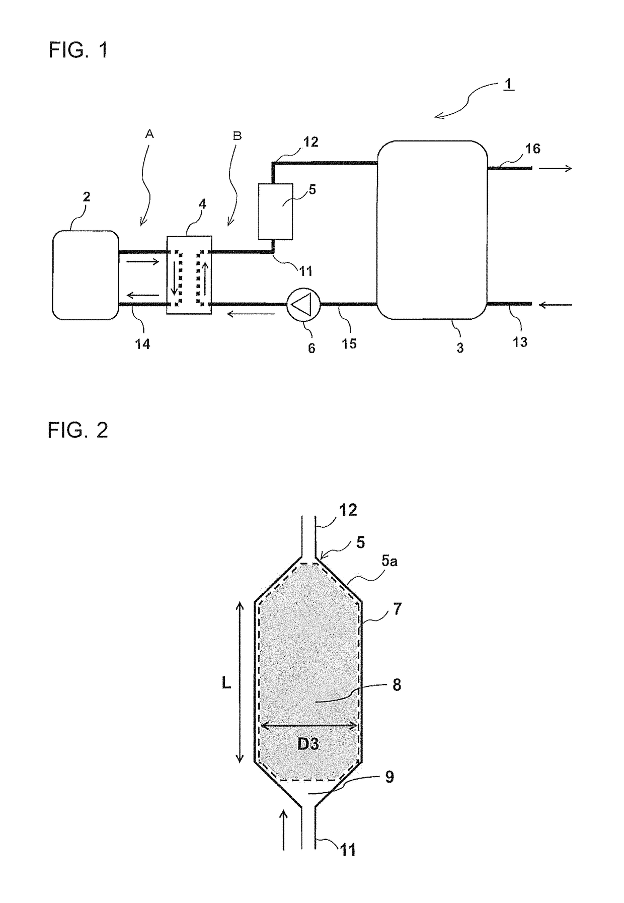
[0041]FIG. 1 is a schematic diagram illustrating a water heater according to Embodiment 1 of the present invention. Firstly, the configuration of a water heater 1 shown in FIG. 1 is briefly described. As shown in FIG. 1, the water heater 1 generally includes a heat source 2 that generates heat for heating water, a heat exchanger 4 that heats water by exchanging heat between the heat generated in the heat source 2 and water, a hot water storage tank 3 that stores water heated in the heat exchanger 4 (hereinafter, heated water is also referred to as hot water), and a scale trapping unit 5 that traps scales (scale particles) from water flowing through the heat exchanger 4.

[0042]In the water heater 1, two circuits (heat medium circulation circuit A and hot water circulation circuit B) are provided. The heat medium circulation circuit A is formed by the heat source 2 and the heat exchanger 4 that are connected to each other by a circulation pipe 14, and supplies heat generated in the hea...

embodiment 2

[0067]The void region of the scale trapping unit 5 shown in Embodiment 1 may be configured as follows. Parts not described in Embodiment 2 are similar to those in Embodiment 1, and parts similar to those in Embodiment 1 are assigned the same reference signs as in Embodiment 1.

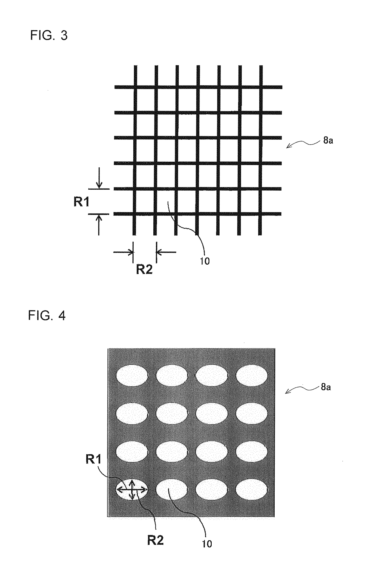
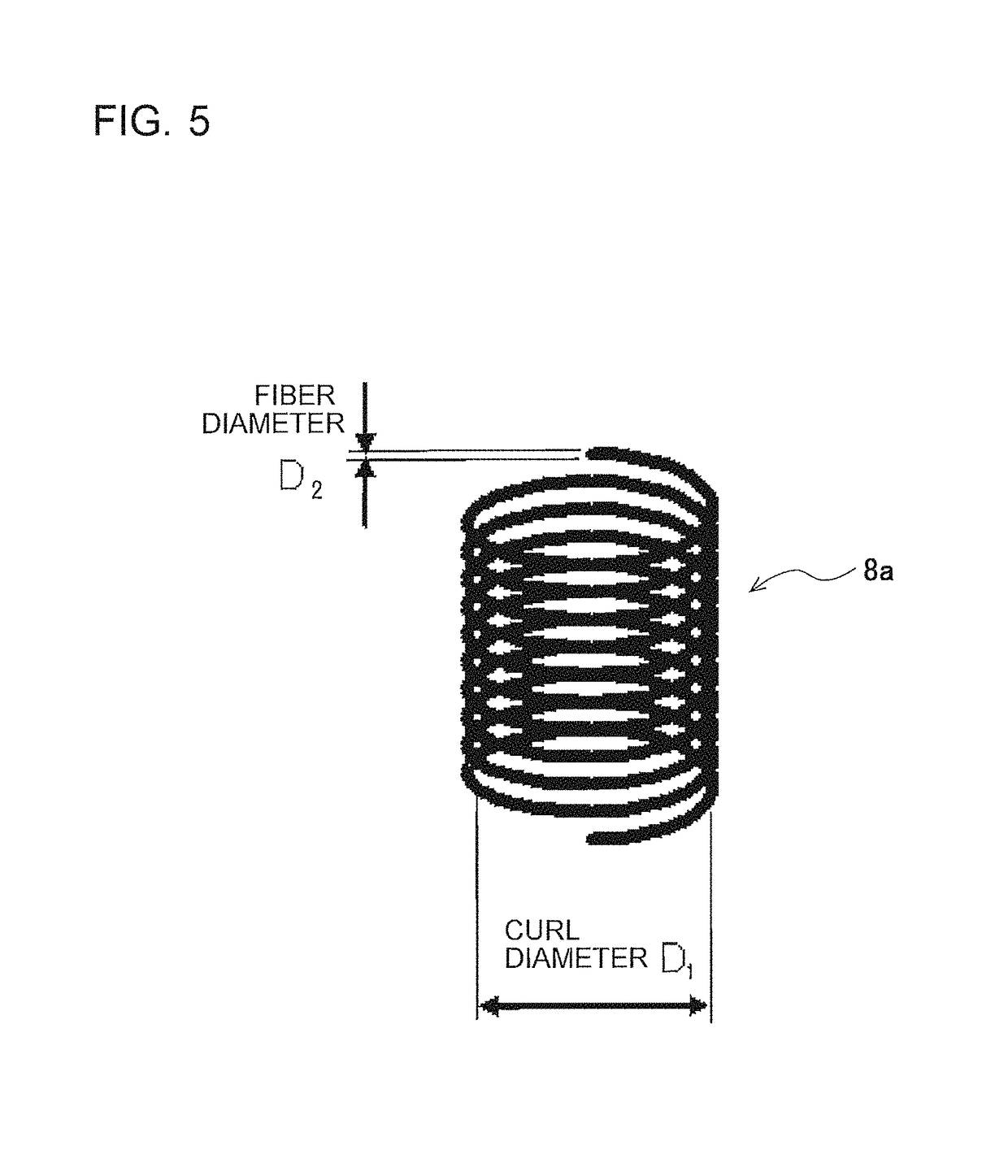
[0068]FIG. 8 is a cross-sectional view of the scale trapping unit 5 according to Embodiment 2 of the present invention. The configuration is similar to that of Embodiment 1 described above except that the forms of the scale adsorbing element 8 (i.e., scale adsorbing element container 7) and the void region 9 in the scale trapping unit 5 are different. The configuration, materials, manner of loading, and other features of the constituent structures 8a, which constitute the scale adsorbing element 8, are also similar to those in Embodiment 1.

[0069]The scale adsorbing element 8 of the scale trapping unit 5 of Embodiment 2 is configured so that the end where the water inlet is located has a recessed shape that is r...

embodiment 3

[0070]Embodiment 3 is to show the design principles of a hollow portion diameter D3 and hollow portion length L (length of the cylindrical portion of the casing 5a, see FIG. 2) of the scale trapping unit 5 of the water heater 1. To ensure that the hot water circulation circuit B has a certain level or more of flow rate, it is necessary to maintain the pressure drop in the scale trapping unit 5 to be at or below a preset value. In this case, the shape and volume of the scale trapping unit 5 define the lower limit of the hollow portion diameter D3 and the upper limit of the hollow portion length L. By configuring the hollow portion diameter D3 and the hollow portion length L so that the pressure drop of the scale trapping unit 5 itself can be reduced even when the volume of the scale trapping unit 5 is the same, it is possible to ensure a certain level or more of flow rate for a more extended period of time even when scale deposit causes pressure drop increase. The scale trapping unit...


PUM

PropertyMeasurementUnit
lengthaaaaaaaaaa
volume ratioaaaaaaaaaa
thicknessaaaaaaaaaa

Abstract

A scale trapping unit includes a casing having a water inlet and a water outlet at respective ends, and a scale adsorbing element loaded in the casing, the scale adsorbing element having opening ports, each of the opening ports having a representative length greater than a length of a scale particle. The casing has a void region at least at the end where the water inlet is located. A scale trapping unit inlet pipe is perpendicularly connected to a central portion of a bottom surface at the end of the casing where the water inlet is located. The scale trapping unit inlet pipe, the void region, and the scale adsorbing element are linearly aligned so that water flows therethrough in a constant direction.

Description

TECHNICAL FIELD[0001]The present invention relates to a scale trapping unit for trapping scale particles and a water heater in which the scale trapping unit is used to inhibit scale particle deposition in a heat exchanger.BACKGROUND ART[0002]Water heaters for supplying hot water to a bathroom, kitchen, or another place can generally be categorized into types such as electric water heaters, gas water heaters, and oil-fired water heaters, all of which include a part called a heat exchanger to transfer heat to water. Among these water heaters, electric water heaters of the heat pump heat exchanger type (heat pump water heater) in particular have recently been of interest from the standpoint of carbon dioxide reduction as measures for energy conservation and against global warming.[0003]The principle of a heat pump water heater is that atmospheric heat is transferred to a heat medium and water is boiled with the heat. Specifically, the principle is based on the repetition (cooling energ...

Claims


Application Information

Patent Timeline
Patent Type & Authority Patents(United States)
IPC IPC(8): C02F5/00C02F1/02F24D17/02C02F1/28F24D19/00C02F1/52
CPCF24D19/0092C02F1/02C02F5/00F24D17/02C02F1/28C02F2001/5218C02F1/001C02F5/02C02F2103/02C02F2303/22
Inventor KAWASHIMA, AYANODA, SEIJIIIJIMA, SHIGERUFURUKAWA, SEIJIMIYA, KAZUHIROSUZUKI, KAZUTAKAMINAMISAKO, HIROKAZU
Owner MITSUBISHI ELECTRIC CORP
Learn More