Optical lens system with a wide field of view

a technology of optical lens and wide field of view, applied in the field of optical lens system, can solve the problems of increased distortion, larger beam, complex lens design, etc., and achieve the effect of reducing the length and extending the field of view of the optical lens system

Active Publication Date: 2017-07-06
NEWMAX TECH
View PDF0 Cites 7 Cited by
  • Summary
  • Abstract
  • Description
  • Claims
  • Application Information

AI Technical Summary

Benefits of technology

[0018]Preferably, a distance along the optical axis between the first lens element and the second lens element is T12, the central thickness of the second lens element along the optical axis is CT2, and they satisfy the following relation: 0.5<T12 / CT2<0.95, so that the field of view of the optical lens system can further be widened.
[0019]Preferably, a distance along the optical axis between the second lens element and the third lens element is T23, a central thickness of the third lens element along the optical axis is CT3, and they satisfy the following relation: 0.05<T23 / CT3<0.7, so that the field of view of the optical lens system can further be widened.
[0020]Preferably, the central thickness of the second lens element along the optical axis is CT2, the central thickness of the third lens element along the optical axis is CT3, and they satisfy the following relation: 0.9<CT3 / CT2<1.9, which can further reduce the length of the optical lens system, and facilitate the molding of the second and third lens elements.
[0021]Preferably, a radius of curvature of the image-side surface of the first lens element is R2, a radius of curvature of the image-side surface of the second lens element is R3, and they satisfy the following relation: 2.4<R2 / R3<3.7, which can reduce the spherical aberration and astigmatism of the optical lens system effectively.
[0022]Preferably, a radius of curvature of the image-side surface of the second lens element is R4, a radius of curvature of the object-side surface of the third lens element is R5, and they satisfy the following relation: −1.55<R4 / R5<−0.5, which can reduce the spherical aberration and astigmatism of the optical lens system effectively.
[0023]Preferably, an Abbe number of the first lens element is V1, an Abbe number of the second lens element is V2, and they satisfy the following relation: 30<V1-V2<42, which can reduce the chromatic aberration of the optical lens system effectively.

Problems solved by technology

The field of view of the lens is usually designed to be 50 to 60 degrees, if over the above designed angle, the aberration will be larger and the lens design will be more complex.
For example, the optical lens systems as disclosed in U.S. Pat. Nos. 8,335,043 and 8,576,497 use two lens groups and 5-6 pieces of lens elements to obtain a wide field of view, however, their distortion is increased.

Method used


Image

  • Optical lens system with a wide field of view
  • Optical lens system with a wide field of view
  • Optical lens system with a wide field of view

Examples


first embodiment

[0038]The equation for the aspheric surface profiles of the respective lens elements of the first embodiment is expressed as follows:

z=ch21+[1-(k+1)c2h2]0.5+Ah4+Bh6+Ch8+Dh10+Eh12+Gh14+…

[0039]wherein:

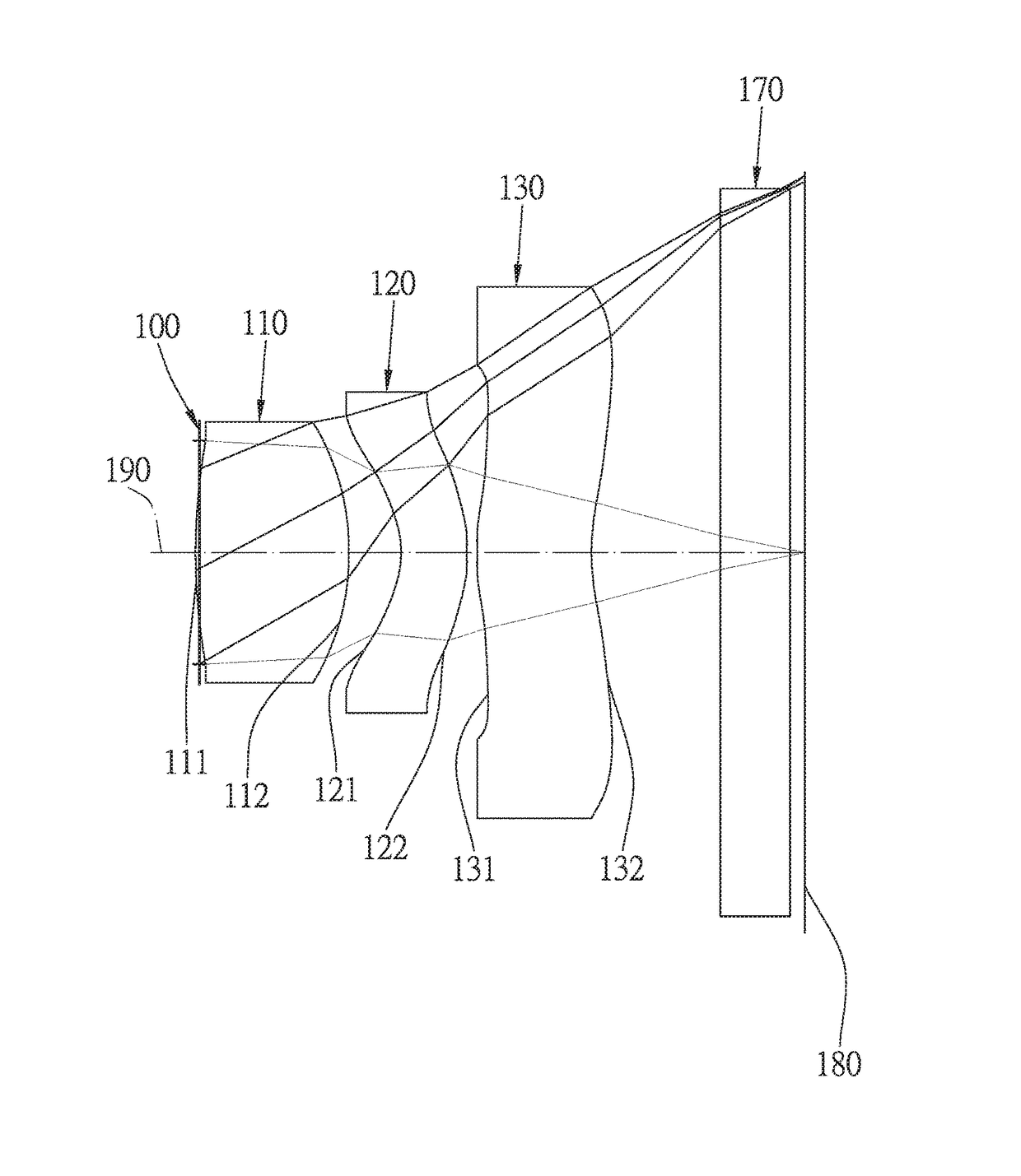
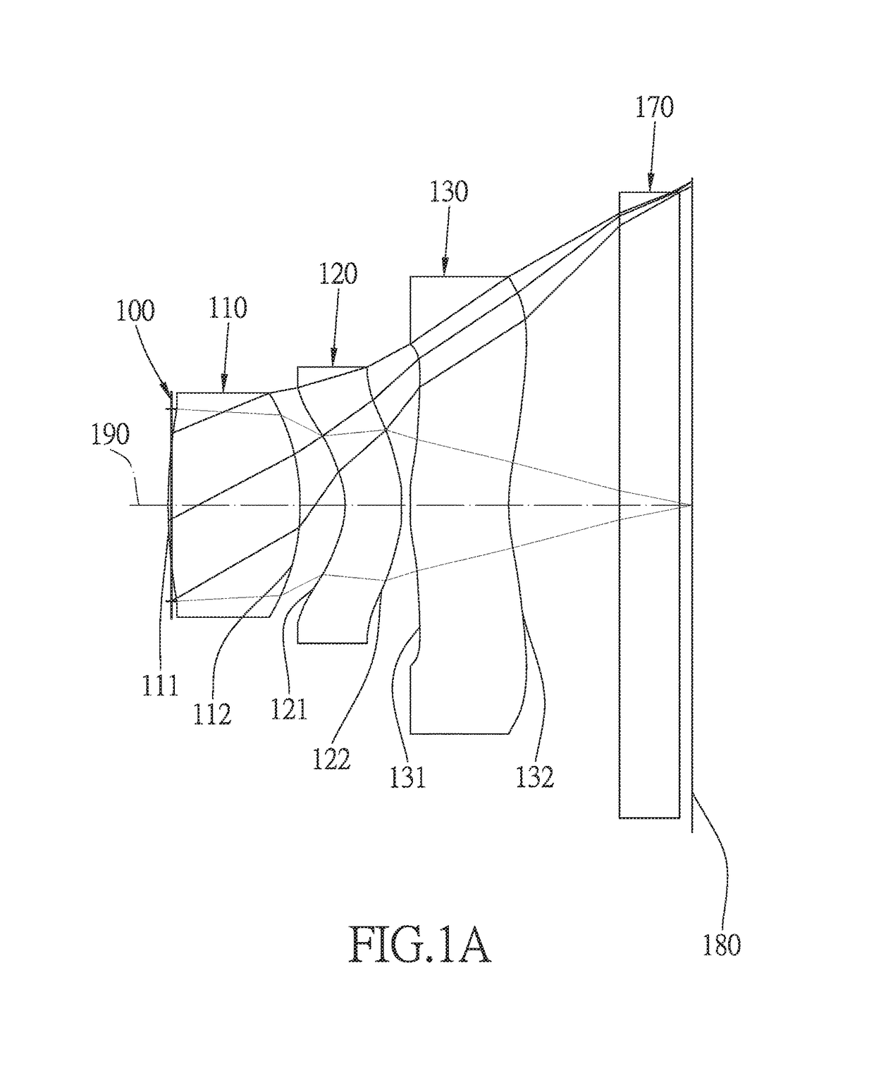
[0040]z represents the value of a reference position with respect to a vertex of the surface of a lens and a position with a height h along the optical axis 190;

[0041]c represents a paraxial curvature equal to 1 / R (R: a paraxial radius of curvature);

[0042]h represents a vertical distance from the point on the curve of the aspheric surface to the optical axis 190;

[0043]k represents the conic constant;

[0044]A, B, C, D, E, G, . . . : represent the high-order aspheric coefficients.

[0045]In the first embodiment of the present optical lens system with a wide field of view, the focal length of the optical lens system with a wide field of view is f, the f-number of the optical lens system with a wide field of view is Fno, the optical lens system with a wide field of view has a maximum view angle...

second embodiment

[0067]The detailed optical data of the second embodiment is shown in table 3, and the aspheric surface data is shown in table 4.

TABLE 3Embodiment 2f(focal length) = 1.24 mm, Fno = 2.0, FOV = 78 deg.FocalSurfaceCurvature RadiusThicknessMaterialindexAbbe #length0ObjectInfinity500.0001Infinity0.0002stopInfinity−0.0253Lens 10.886 (ASP)0.331Plastic1.54456.0001.0744−1.466 (ASP)  0.1215Lens 2−0.421 (ASP)  0.192Plastic1.65121.500−2.2916−0.694 (ASP)  0.1637Lens 30.477 (ASP)0.251Plastic1.53556.0003.14080.547 (ASP)0.3409IR-filterInfinity0.210Glass1.51764.167—10Infinity0.15011ImageInfinityInfinity

TABLE 4Aspheric Coefficientssurface#345K =−1.9566E+001.1982E+01−2.5128E−01A =−5.4445E−01−2.8218E+00−4.2590E+00B =1.2215E+00−2.2349E+005.6898E+01C =−7.7254E+002.1695E+016.5023E+01D =−6.2292E+022.5877E+023.6131E+02E =−1.5113E+041.7908E+03−1.1856E+04F =1.4333E+05−4.8661E+034.0487E+04surface#678K =8.9298E−01−5.8224E+00−3.6944E+00A =−4.1282E+00−2.0766E+00−1.8624E+00B =4.4471E+016.0519E+005.3892E+00C =2.9344...

third embodiment

[0076]The detailed optical data of the third embodiment is shown in table 5, and the aspheric surface data is shown in table 6.

TABLE 5Embodiment 3f(focal length) = 1.311 mm, Fno = 2.0, FOV = 84 deg.FocalSurfaceCurvature RadiusThicknessMaterialindexAbbe #length0objectInfinityInfinity1Infinity0.0002stopInfinity−0.0013Lens 1  1.424 (ASP)0.547plastic1.54456.0000.9374−0.690 (ASP)0.2035Lens 2−0.257 (ASP)0.236plastic1.65121.500−1.6126−0.463 (ASP)0.0307Lens 3  0.701 (ASP)0.345plastic1.54456.0002.7348  1.091 (ASP)0.1209IR filterInfinity0.145glass1.51764.167—10Infinity0.13011CoverInfinity0.4glass1.51764.167—glass12Infinity0.04513ImageInfinityInfinity

TABLE 6Aspheric Coefficientssurface#345K =1.7206E+00−1.0243E−01−2.3651E+00A =−7.4912E−01−3.7511E−01−3.7050E+00B =3.0527E+00−5.9026E+002.8943E+00C =−1.5457E+02−2.8241E+002.3647E+02D =2.2136E+034.9721E+02−1.1944E+03E =−1.8019E+04−2.7550E+031.4902E+03F =5.5048E+044.1785E+039.2168E+02surface#678K =−4.8653E+00−2.2993E−01−5.9393E−01A =−2.7900E+00−2.0212...


PUM


Abstract

An optical lens system with a wide field of view includes, in order from the object side to the image side: a stop, a first lens element with a positive refractive power, a second lens element with a negative refractive power, and a third lens element with a positive refractive power. A focal length of the first lens element and the second lens element combined is f12, a focal length of the third lens element is f3, and they satisfy the relation: 0.3<f12/f3<0.9, so that the optical lens system has a wide field of view, high resolution, short length and less distortion.

Description

BACKGROUND OF THE INVENTION[0001]Field of the Invention[0002]The present invention relates to an optical lens system, and more particularly to a miniaturized three-piece optical lens system with a wide field of view.[0003]Related Prior Art[0004]In recent years, with the popularity of electronic products with the function of taking photographs, there's an increasing demand for an optical lens system. In order to obtain a wider shooting range, the lens angle should meet certain requirements. The field of view of the lens is usually designed to be 50 to 60 degrees, if over the above designed angle, the aberration will be larger and the lens design will be more complex. For example, the optical lens systems as disclosed in U.S. Pat. Nos. 8,335,043 and 8,576,497 use two lens groups and 5-6 pieces of lens elements to obtain a wide field of view, however, their distortion is increased. The optical lens systems as disclosed in U.S. Pat. Nos. 8,593,737, 8,576,497 and 8,395,853 also have a wi...

Claims


Application Information

Patent Timeline
Patent Type & Authority Applications(United States)
IPC IPC(8): G02B13/00G02B27/00G02B5/20G02B9/16
CPCG02B13/0035G02B9/16G02B5/208G02B27/0081G02B27/0025
Inventor LEE, CHUN-SHENG
Owner NEWMAX TECH
Why Eureka
Try Eureka