LCD Improving Color Shift at Large Viewing Angle

Active Publication Date: 2017-07-06
TCL CHINA STAR OPTOELECTRONICS TECH CO LTD +1
View PDF7 Cites 2 Cited by
  • Summary
  • Abstract
  • Description
  • Claims
  • Application Information

AI Technical Summary

Benefits of technology

[0024]Comparing to current technology, the present invention provides a LCD with an asymmetrical black matrix layer. The width of the black matrix unit on both sides of the filter unit of high transmittance rate (e.g. green or white filter unit) is larger than that of the black matrix unit between two filter unit of low transmittance rate (e.g. red or blue filter unit). More specifically, when the asymmetrical black matrix layer locates on the side that is away from the backlight module (i.e. close to viewers), the width of the black matrix unit facing the filter unit of high transmittance rate is larger than that

Problems solved by technology

However, a liquid crystal display (LCD) with a wide viewing angle usually has a problem: color shift at large viewing angles.
It is mainly because of light leakage of adjacent pixels that affect

Method used


Image

  • LCD Improving Color Shift at Large Viewing Angle
  • LCD Improving Color Shift at Large Viewing Angle
  • LCD Improving Color Shift at Large Viewing Angle

Examples


first embodiment

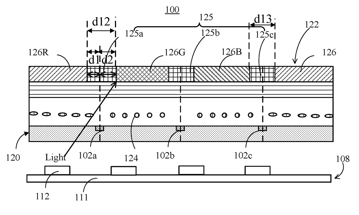
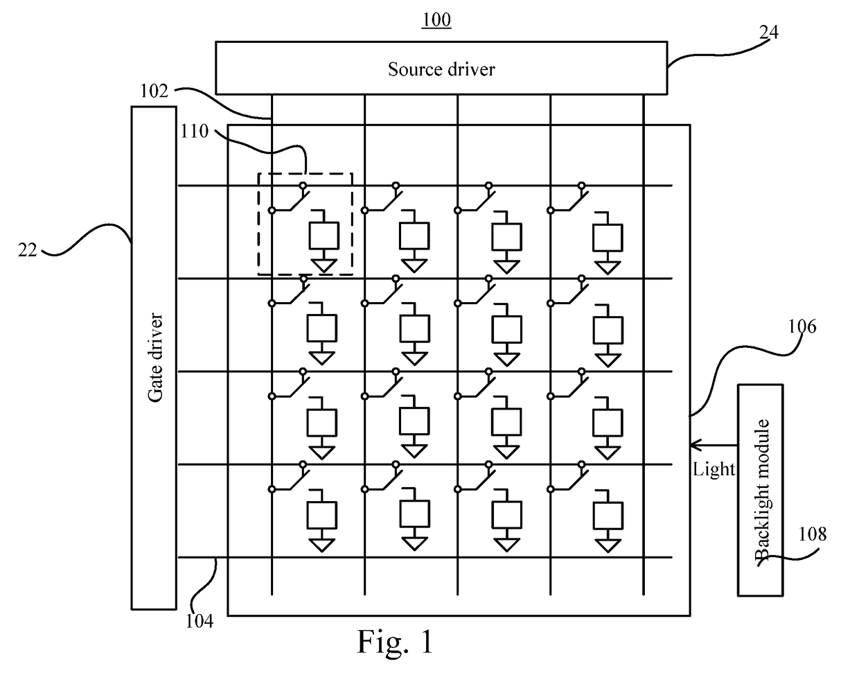
[0034]Please refer to FIG. 1 and FIG. 2. FIG. 1 is a schematic diagram of a LCD 100 of the present invention. FIG. 2 is a cross-sectional view of the LCD 100 of the present invention. The LCD 100 of the present invention comprises a LCD panel 106 and a backlight module 108. The LCD panel 106 comprises an array substrate 120, a color filter layer 122 and a liquid crystal layer 124. The liquid crystal layer 124 locates between the array substrate 120 and color filter layer 122. The color filter layer 122 comprises a black matrix layer 125 and a color film layer 126. The LCD panel 106, through the color film layer 126, separates the light into three primary colors, red, green and blue, so to show color images. The black matrix layer 125 is for preventing light leakage. The array substrate 120 comprises a plurality of data lines 102, scan lines 104 and pixel units 110 arranged in arrays. Each pixel unit 110 electrically connects to one data line 102 and one scan line 104. The backlight ...

second embodiment

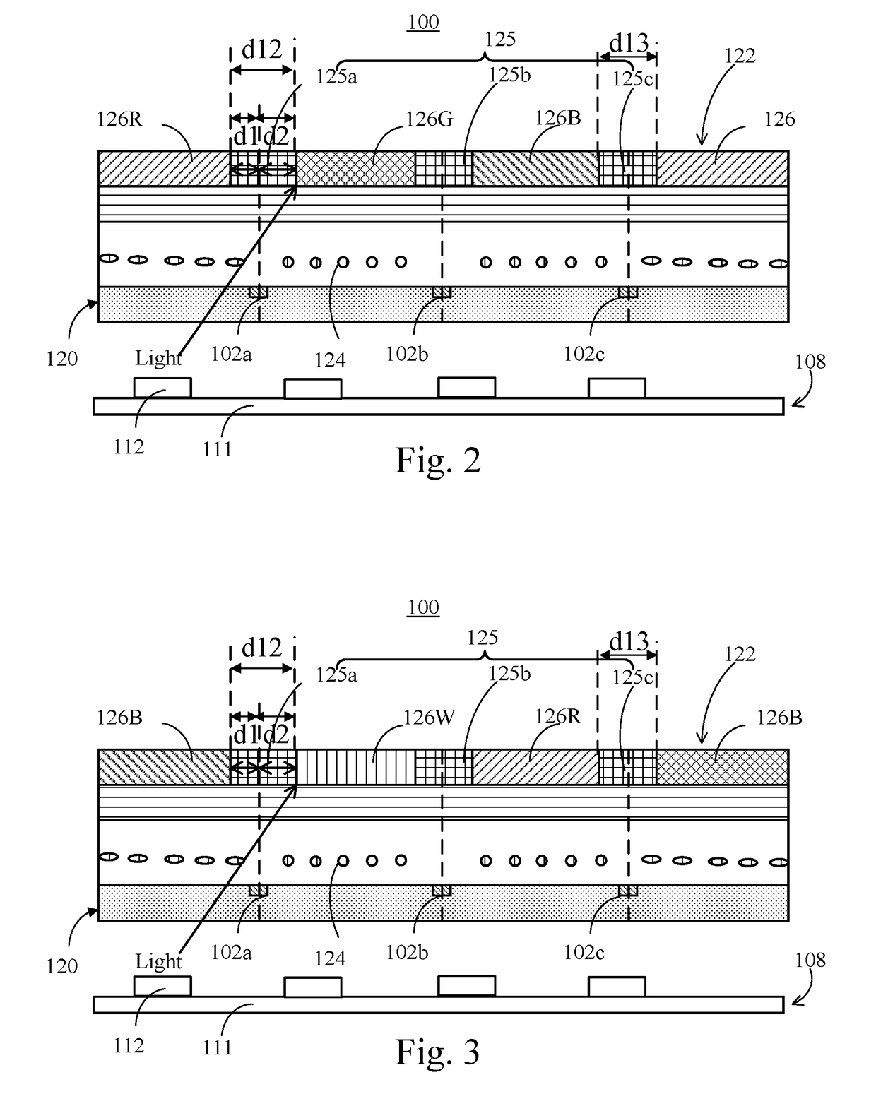
[0038]Please refer to FIG. 3. FIG. 3 is a cross-sectional view of the LCD 100 of the present invention. The color filter layer 126 can comprise a white filter unit 126W, a red filter unit 126R and a blue filter unit 126B. The transmittance rate of the white filter unit 126W that filters the white light is larger than the red filter unit 126R and blue filter unit 126B. Therefore, the white filter unit 126W and green filter unit 126G can serve as the second filter unit of high transmittance rate. The white filter unit 126W is between the red filter unit 126R and blue filter unit 126B.

[0039]The black matrix layer 125 comprises a plurality of black matrix units comprising black matrix units 125a, 125b, and 125c. The black matrix unit 125a connects between the white filter unit 126W and blue filter unit 126B and aligns to a data line 102a; the black matrix unit 125b connects between the white filter unit 126W and the red filter unit 126R and aligns to a data line 102b; the black matrix u...

third embodiment

[0040]Please refer to FIG. 4. FIG. 4 is a cross-sectional view of the LCD 100 of the present invention. Items in FIG. 4 marked with numbers the same as those in FIG. 2 have the same functions, so no further explanation is provided here. A width d13 of the black matrix unit 125c is smaller than not only a width d12 of the black matrix unit 125a, but also a width d23 of the black matrix unit 125b. A width d2 of the black matric unit 125a facing the green filter unit 126G is larger than a width d1 of the black matric unit 125a facing the red filter unit 126R. The black matrix unit 125b aligns to and bases on the center line of the data line 102b, with a width d2′ facing the green filter unit 126G larger than a width d3 facing the blue filter unit 126B. The width d2′ can equal to the width d2. Or, the proportion of d2′ to d2 can be adjusted according to the transmittance ratio of the red filter unit 126R to green filter unit 126G, and the transmittance ratio of the blue filter unit 126B...


PUM


Abstract

An LCD includes a backlight module, an array substrate, and a color filter layer. The color filter layer includes a first filter unit, a second filter unit and a black matrix unit. A transmittance rate of the second filter unit is larger than that of the first filter unit. The black matrix layer is connected between the first filter unit and second filter unit. The width of the black matrix unit is larger than that of the third black matrix unit. The width of the black matrix unit facing the first filter unit is larger than that of the black matrix unit facing the second filter unit. This kind of asymmetrical black matrix layer not only best prevents lowering the pixel aperture ratio, but also improves color shift of images when light goes through pixels of low transmittance as pixels of high transmittance are turned off.

Description

BACKGROUND OF THE INVENTION[0001]1. Field of the Invention[0002]The present invention relates to a liquid crystal display (LCD), and more specifically, to a LCD that improves color shift at large viewing angle by adjusting the width of black matrix layers.[0003]2. Description of the Prior Art[0004]As display technology advances, people pay more and more attention to the display quality of display devices, which are developing wider viewing angles. However, a liquid crystal display (LCD) with a wide viewing angle usually has a problem: color shift at large viewing angles. It is mainly because of light leakage of adjacent pixels that affects color purity shown by pixels. For example, when the LCD shows a red image, the light goes through red pixels and adjacent green pixels are turned off. But some light still goes through the green pixels and thus the red image, when seen from a large viewing angle, has a yellowish color.[0005]In addition, the resolution of LCDs gets higher and highe...

Claims


Application Information

Patent Timeline
IPC IPC(8): G02F1/1335G02F1/1362
CPCG02F1/133512G02F1/136286G02F1/133514G02F1/136209G02F1/136222
Inventor TANG, YUEJUNLI, DEJIUNCUI, HONGQINGYANG, TSUNGYING
Owner TCL CHINA STAR OPTOELECTRONICS TECH CO LTD
Why Eureka
Try Eureka