Plug connecetor with a metallic enclosure having heat sink member thereon

a technology of heat sink member and connector, which is applied in the manufacture of contact member cases/bases, coupling device connections, electrical apparatus construction details, etc., can solve the problems of occupying too much surface area of metal shell, unfavorable manufacturing, etc., and achieve good heat dissipation performance and dissipation of hea

Active Publication Date: 2017-07-06
FOXCONN INTERCONNECT TECHNOLOGY LIMITED
View PDF14 Cites 14 Cited by
  • Summary
  • Abstract
  • Description
  • Claims
  • Application Information

AI Technical Summary

Benefits of technology

[0009]According to the present invention, a thermal pad sandwiched between the set of electronic components and the metallic enclosure to dissipate heat from the electronic component to the metallic enclosure and eventually to the air via the heat sink member, therefore, the plug connector having good heat dissipation performance.

Problems solved by technology

Anyhow, the unitary structure on the shell may be not beneficial for manufacturing, or may occupy too much surface of the metal shell.

Method used


Image

  • Plug connecetor with a metallic enclosure having heat sink member thereon
  • Plug connecetor with a metallic enclosure having heat sink member thereon
  • Plug connecetor with a metallic enclosure having heat sink member thereon

Examples


first embodiment

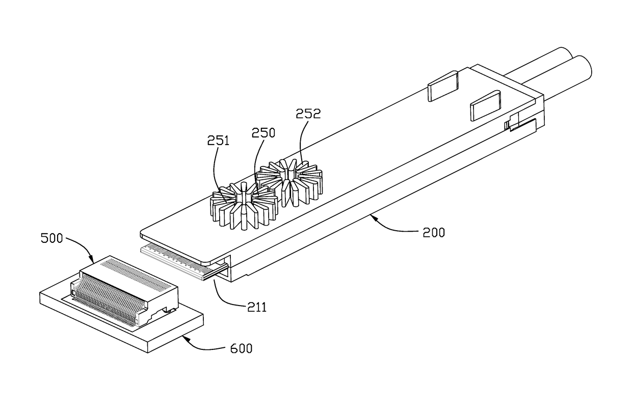
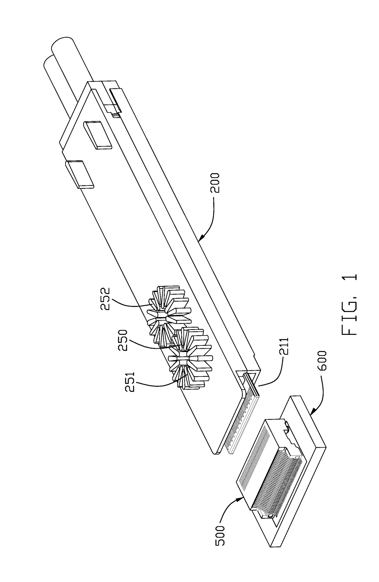
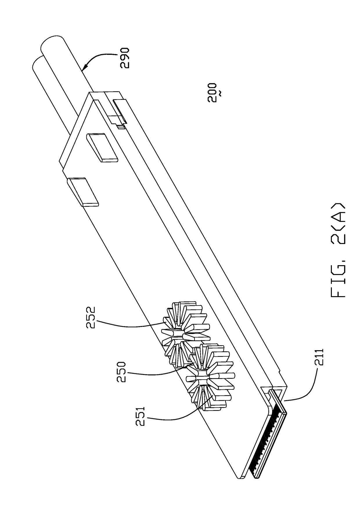
[0062]Referring to FIGS. 1 to 8, 12 and 13, this invention includes a cable connector or a plug connector 200 mated with a receptacle connector 500 mounted upon a printed circuit board 600. The cable connector 200 includes a metallic enclosure 210 with a heat sink member 250 exposed on an exterior surface to enclose a printed circuit board 280 with electronic components 282 thereon. A thermal pad 284 is sandwiched between the electronic component 282 and the metallic enclosure 210 to dissipate heat from the electronic component 282 to the metallic enclosure 210 and eventually to the air via the heat sink member 250. A plurality of pads 286, which are shown in FIG. 8 rather than in other figures, are formed on a front region of the printed circuit board 280.

[0063]An attachment connection unit 220 includes a plurality of contacts 222 respectively soldered upon the corresponding pads 286 and an insulative housing 224 enclosing the contacts 222 and the front region of the printed circui...

fourth embodiment

[0070]Referring to FIGS. 24(A)-32(B) and 35, this invention includes a cable connector or a plug connector 700 mated with a receptacle connector 800 adapted mounted upon a printed circuit board (not shown). The cable connector 700 includes a metallic enclosure 710 with a detachably attached heat sink member 750 to enclose a printed circuit board 780 with electronic components 782 thereon wherein the enclosure 710 includes upper and lower parts assembled to each other in the vertical direction. In this embodiment, the metallic enclosure 710 forms an opening 714 in a top wall to receive the heat sink member 750 therein. The heat sink member 750 includes associatively a thermal portion 752 thereunder. A thermal pad 784 is sandwiched between the electronic component 782 and the heat sink member 750 to dissipate heat from the electronic component 782 to the heat sink member 750. Notably, the thermal portion 752 and the thermal pad 784 are of the same character so as to be deemed as one p...

fifth embodiment

[0073]Alternately, the plug connector 300 in accordance with present invention shown in FIGS. 33(A) and 33(B) discloses the heat sink member 350 equipped with a pair of locking ears 352 and a latch 354 to be downwardly assembled into the opening 314 of the 310 firstly wherein the locking ears 352 are aligned with the corresponding cutouts 312 in the metallic enclosure 310, and successively to be moved forwardly so as to have the locking ears 352 and the latch 354 engaged with an underside of the top wall of the metallic enclosure 310. Finally, a stuffer / blocker 360 is inserted into the remaining portion of the opening 314 behind the heat sink member 350 for preventing backward movement of the heat sink member 350. To replace the heat sink member 350, two arms of the blocker 360 are inwardly deflected to each other to disengage the blocker 360 from the metallic enclosure 310, and moved upwardly so as to allow the heat sink member 350 to be withdrawn initially backwardly / horizontally ...


PUM


Abstract

A plug connector includes a metallic enclosure with a heat sink member exposed on an exterior surface to enclose a printed circuit board; a set of electronic components assembled upon the printed circuit board; a thermal pad sandwiched between the set of electronic components and the metallic enclosure to dissipate heat from the electronic component to the metallic enclosure and eventually to the air via the heat sink member; wherein a center of said heat sink member is essentially aligned with a center of said set of electronic components or a center of the thermal pad for efficient dissipation of heat.

Description

BACKGROUND OF THE INVENTION[0001]1. Field of the Invention[0002]The invention relates to a plug connectors, and particularly to the plug connector with a heat sink structure.[0003]2. Description of Related Art[0004]U.S. Publication No. US20160149324, published to Regnier on May 26, 2016, discloses a plug connecter to be mated with a receptacle connector. The plug connector comprises a metal shell, and a printed circuit board received in the metal shell. The metal shell comprises a unitarily formed heat sink thereon to be mated with the receptacle connector. Anyhow, the unitary structure on the shell may be not beneficial for manufacturing, or may occupy too much surface of the metal shell.[0005]An improved plug connector is desired to offer advantages over the related art.SUMMARY OF THE INVENTION[0006]An object of the present invention is to provide a plug connector having good heat dissipation performance.[0007]To achieve the above-mentioned object, a plug connector comprises a met...

Claims


Application Information

Patent Timeline
Patent Type & Authority Applications(United States)
IPC IPC(8): H01R13/66H05K1/18H05K1/02H01R12/72H01R43/18
CPCH01R13/665H01R12/721H05K2201/06H05K1/0203H05K1/181H01R43/18H01R13/6658H05K7/20409H05K7/20445H01R24/00G02B6/4269H01L23/467H05K5/0047H05K7/20436H05K13/0486
Inventor LITTLE, TERRANCE F.YANG, AN-JENZHAO, JIMZHANG, YUANZHENG, JIECHEN, KE-HAOZHANG, YU
Owner FOXCONN INTERCONNECT TECHNOLOGY LIMITED
Why Eureka
Try Eureka