Eureka AIR delivers breakthrough ideas for toughest innovation challenges, trusted by R&D personnel around the world.

Torque control of a vehicle powertrain based on a time derivative for a dynamic torque

Active Publication Date: 2017-07-13
SCANIA CV AB
View PDF0 Cites 5 Cited by
  • Summary
  • Abstract
  • Description
  • Claims
  • Application Information

AI Technical Summary

Benefits of technology

The present invention allows for the rapid changes in the dynamic torque to be made, making it easier to optimize the control of the vehicle's performance and driver comfort. It also reduces powertrain oscillations, which can cause rocking of the vehicle and discomfort for the driver. Additionally, the invention reduces wear of the powertrain, resulting in a longer life for the vehicle.

Problems solved by technology

These rocking movements in the vehicle are very disruptive for the driver of the vehicle.
The torque ramps which are used today when an engine torque is requested thus introduce a limit to how the torque may be requested by the engine in the vehicle.
Allowing the driver and / or, for example, a cruise control to freely request a torque would, with current art systems, often give rise to considerable and disruptive powertrain oscillations, which is why limiting torque ramps are used.
However, static torque ramps have a number of disadvantages, relating to the fact that they are not optimized to all driving events that the vehicle may be exposed to.
For certain driving modes, the static and limited torque ramps give rise to a reduction in vehicle performance, as, due to the torque ramp, the requested torque is unnecessarily low for driving modes, wherein it would have been possible to request more engine torque without the occurrence of powertrain oscillations.
For other driving modes, the torque ramp does not limit the requested torque sufficiently, which means that powertrain oscillations occur and therefore rocking movements in the vehicle.
Therefore, the use of torque ramps, for certain driving modes, provides non-optimal torques, which may give rise to an unnecessary reduction in vehicle performance and / or rocking that reduces the comfort, caused by powertrain oscillations.

Method used


Image

  • Torque control of a vehicle powertrain based on a time derivative for a dynamic torque
  • Torque control of a vehicle powertrain based on a time derivative for a dynamic torque
  • Torque control of a vehicle powertrain based on a time derivative for a dynamic torque

Examples


Embodiment Construction

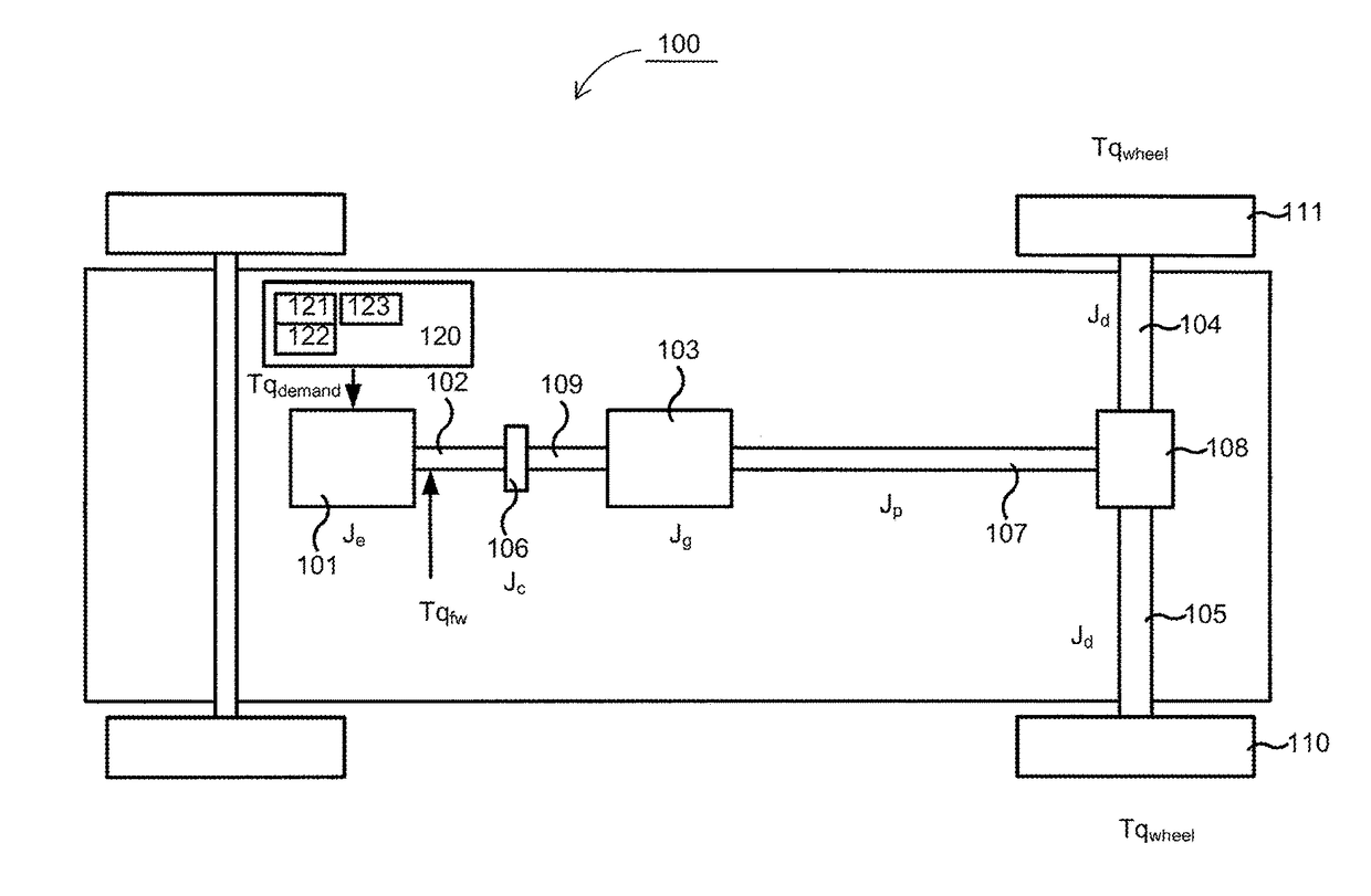
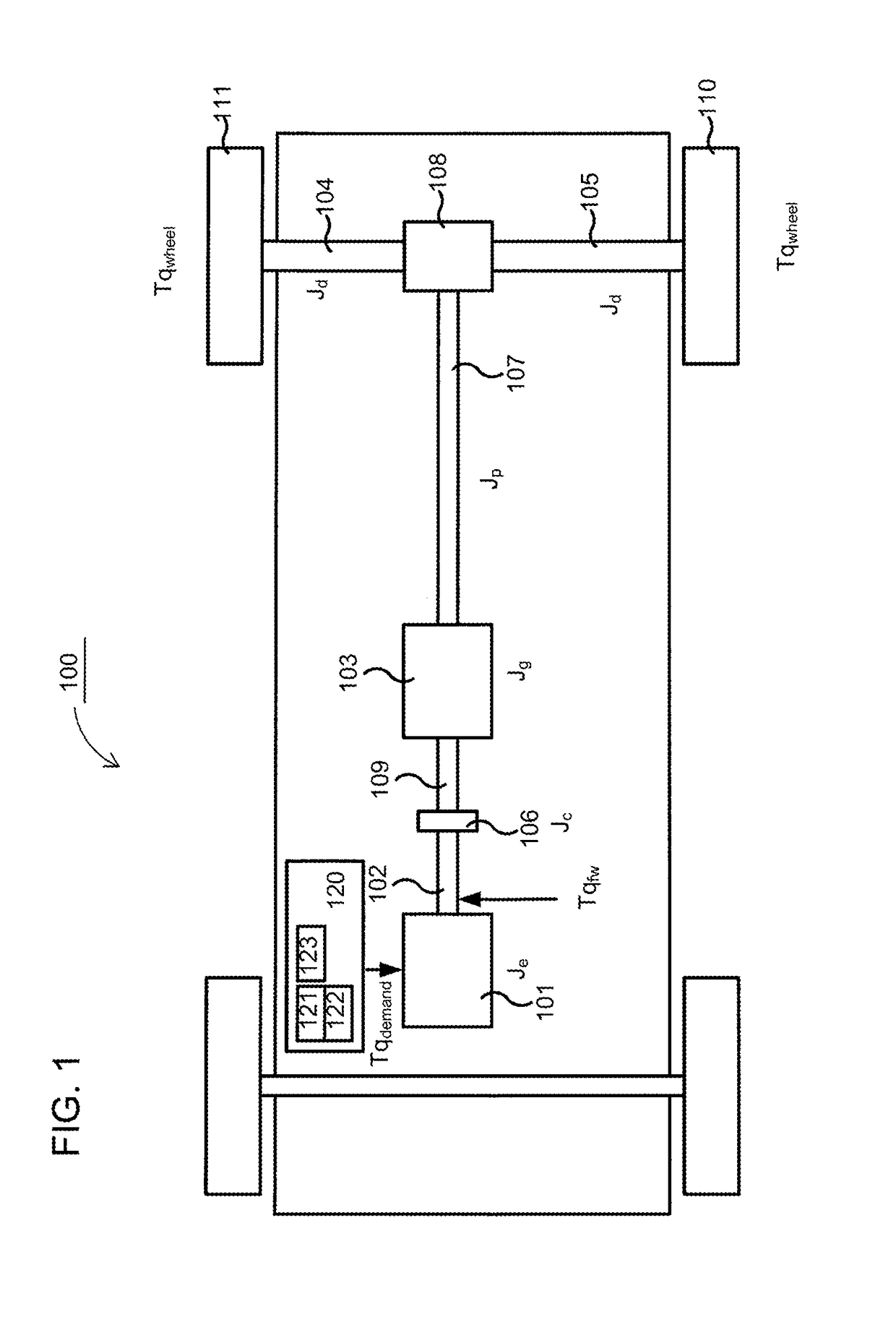
[0027]FIG. 1 schematically shows a heavy example vehicle 100, such as a truck, a bus or similar, which will be used to explain the present invention. The present invention is, however, not limited to use in heavy goods vehicles, but may also be used in lighter vehicles such as cars. The vehicle 100 shown schematically in FIG. 1 comprises a pair of driving wheels 110, 111. The vehicle furthermore comprises a powertrain with an engine 101, which may be for example a combustion engine, an electrical motor or a combination of these, a so called hybrid. The engine 101 may, for example, in a customary fashion, via an output shaft 102 on the engine 101, be connected with a gearbox 103, possibly via a clutch 106 and an input shaft 109 connected to the gearbox 103. An output shaft 107 from the gearbox 103, also known as a propeller shaft, drives the driving wheels 110, 111 via a final gear 108, such as e.g. a customary differential, and drive shafts 104, 105 connected with said final gear 10...


PUM


Abstract

A desired change of a time derivative of dynamic torque (Tqfw), provided to an output shaft from an engine in a vehicle, from a current value to a new desired value is determined. A current rotational speed difference (Δωpres) is determined between a first end of the powertrain in a vehicle, which rotates with a first rotational speed (ω1), and a second end of the powertrain, which rotates with a second rotational speed. The first rotational speed (ω1) is then controlled on the basis of the desired value of the time derivative for the dynamic torque (Tqfw), a spring constant (k) related to a torsional compliance in the powertrain, and the determined current rotational speed difference {Δωpres). Through control of the first rotational speed, the current value for the time derivative for the dynamic torque is also indirectly controlled towards the desired value.

Description

CROSS-REFERENCE TO RELATED APPLICATIONS[0001]The present application is a 35 U.S.C. §§371 national phase conversion of PCT / SE2015 / 050598, filed May 25, 2015, which claims priority of Swedish Patent Application No. 1450655-4, filed May 30, 2014, the contents of which are incorporated by reference herein. The PCT International Application was published in the English language.TECHNICAL FIELD[0002]The present invention relates to a system for control of a change in a time derivative ΔT′qfw for a dynamic torque. The present invention also relates to a method for control of a change in a time derivative ΔT′qfw for a dynamic torque, and a computer program and a computer program product, which implement the method according to the invention.BACKGROUND[0003]The following background description constitutes a description of the background to the present invention, which does not, however, necessarily constitute prior art.[0004]Vehicles, for example cars, buses and trucks, are driven forward b...

Claims


Application Information

Patent Timeline
IPC IPC(8): B60W30/20B60W30/18B60W30/188
CPCB60W30/20B60W30/188B60W30/18027B60W2030/206B60W2510/0657B60W2510/083B60W2720/28B60W2710/083B60W2720/30B60W2520/30B60W2510/0638B60W2710/0644B60W2520/28B60W2710/0666B60W50/06F02D41/021F02D41/0225F02D41/10F02D41/1401F02D41/1497B60W2710/0672F02D2041/1431F02D2041/1432F02D2200/1002F02D2200/101F02D2200/50F02D2200/501F02D2250/18B60W10/06F02D2250/28
Inventor REDBRANDT, KARLEVALDSSON, MARTIN
Owner SCANIA CV AB
Why Eureka
Eureka Blog
Learn More