Eureka AIR delivers breakthrough ideas for toughest innovation challenges, trusted by R&D personnel around the world.

Device and method for peening by coupling laser shock wave and ultrasonic shock wave in real time

a laser shock wave and ultrasonic shock wave technology, applied in the field of laser processing, can solve the problems of low residual compressive stress, poor peening/forming effect, and low degree of grain refinement on the surface of the par

Active Publication Date: 2022-08-04
JIANGSU UNIV
View PDF5 Cites 0 Cited by
  • Summary
  • Abstract
  • Description
  • Claims
  • Application Information

AI Technical Summary

Benefits of technology

This patent describes a device and method for peening materials by coupling a laser shock wave and an ultrasonic shock wave. By adjusting the initial times, rotation angles, and velocities of the ultrasonic shock devices, the device can control the directions and wavefront positions of the shock waves in real-time, making up for the difference in propagation velocities of the two shock waves. This results in a continuous atomic dense area on the path of the laser shock wave, increasing the amplitude and time of the shock wave in the material, improving the peening or forming effect of metal materials. The present invention expands the control ranges of the amplitudes, space, and time distributions of the shock waves in the material, further improving the peening or forming effect of metal materials.

Problems solved by technology

However, the shock wave induced by the laser beam alone has low amplitude and short time, resulting in a low residual compressive stress and a low degree of grain refinement on the surface of the part, which leads to a poor peening / forming effect and poor controllability.
(1) The vibrator ages the entire sample, but it cannot achieve local peening.
(2) The LSP and the vibration aging are performed separately, which cannot overcome the technical defects of low amplitude and short time of the laser shock wave, resulting in low plastic deformation and low residual compressive stress, thereby leading to a poor peening effect.
However, because the propagation velocity of the laser shock wave is much higher than that of the ultrasonic shock wave, the device does not realize the real-time coupling of the laser shock wave and the ultrasonic shock wave.
Therefore, it does not solve the technical defects of low amplitude and short time of the laser shock wave, which results in low plastic deformation and low residual compressive stress.
(1) It does not make up for the difference in the propagation velocities of the laser shock wave and the ultrasonic shock wave or realize the real-time coupling of the laser shock wave and the ultrasonic shock wave, resulting in the periodic atomic sparse areas on the path of the laser shock wave.
(2) The atomic sparse areas reduce the amplitude of the laser shock wave, and although they promote grain refinement, they reduce plastic deformation and residual compressive stress, thereby weakening the peening effect.
However, this patent does not make up for the difference in the propagation velocities of the laser shock wave and the ultrasonic shock wave, and fails to realize the real-time coupling of the laser shock wave and the ultrasonic shock wave.
Therefore, it cannot overcome the technical defects of low amplitude and short time of the laser shock wave, which results in low plastic deformation and low residual compressive stress.

Method used


Image

  • Device and method for peening by coupling laser shock wave and ultrasonic shock wave in real time
  • Device and method for peening by coupling laser shock wave and ultrasonic shock wave in real time
  • Device and method for peening by coupling laser shock wave and ultrasonic shock wave in real time

Examples


embodiment 1

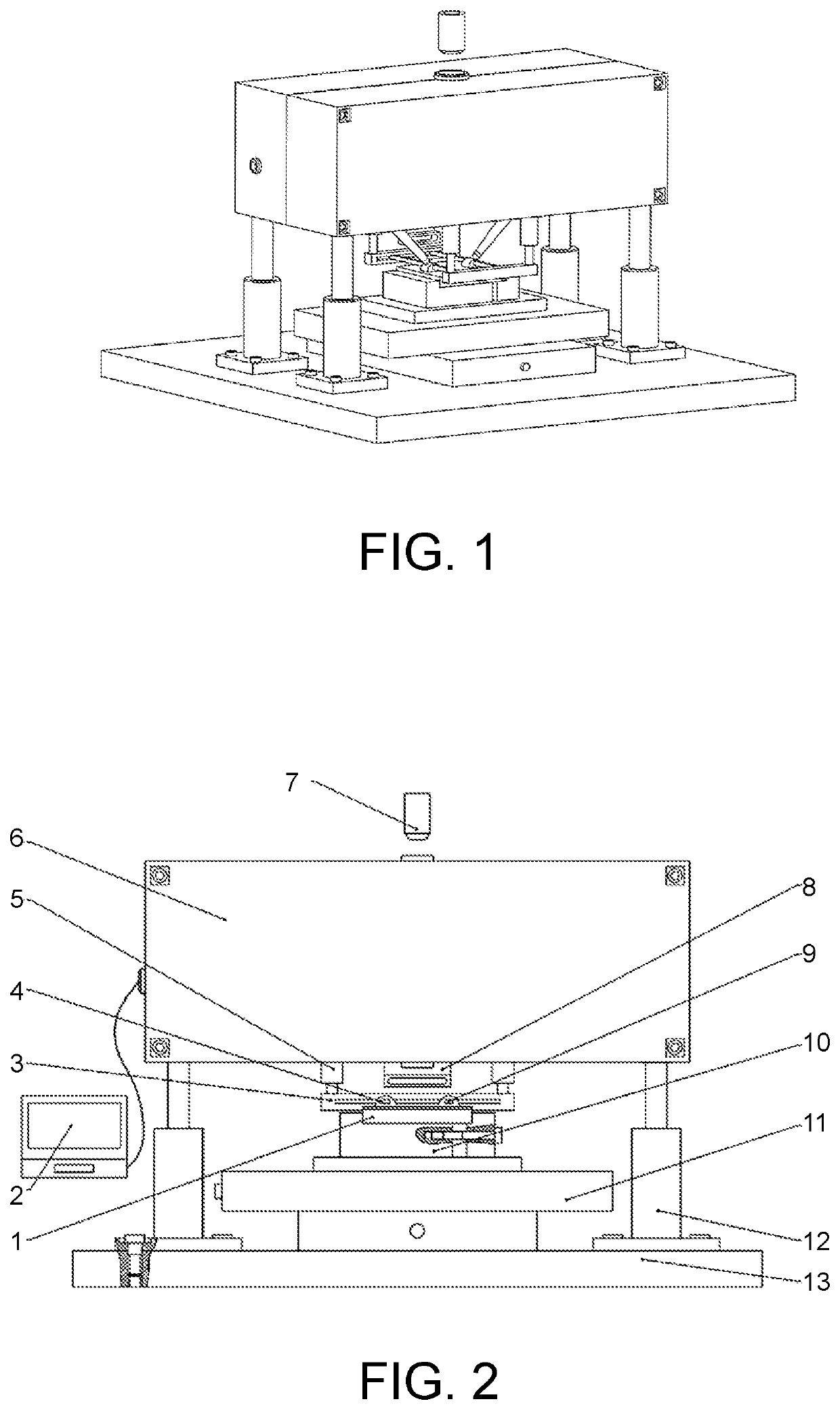
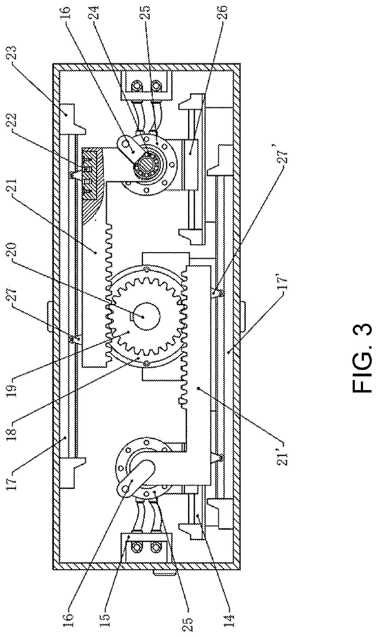
[0048]The present invention provides a device for peening by coupling a laser shock wave and an ultrasonic shock wave in real time. As shown in FIG. 1, FIG. 2 and FIG. 3, the device includes a synchronization device, a laser device, two ultrasonic shock devices, a working platform and a control system. The working platform includes an upper casing 6, first hydraulic cylinders 5, second hydraulic cylinders 12, limiting slide rails 3, and a base 13. A workpiece 1 is clamped on a fixture platform 10. A movable platform 11 and the base 13 are sequentially arranged from top to bottom, such that the workpiece 1 moves linearly in X-axis and Y-axis directions.

[0049]The upper casing 6 is supported above the base 13 through the second hydraulic cylinders 12. Two supporting beams 9 are provided under the upper casing 6 through the second hydraulic cylinders 12. The two supporting beams 9 are respectively connected to the limiting slide rails 3 through sliding pairs. The limiting slide rails 3 ...

embodiment 2

[0077]The device for peening by coupling the laser shock wave and the ultrasonic shock wave in real time is used to peen a 2024-T351 aluminum alloy sheet with a thickness of 2 mm. The specific process is as follows.

[0078]ΔT is calculated as follows.

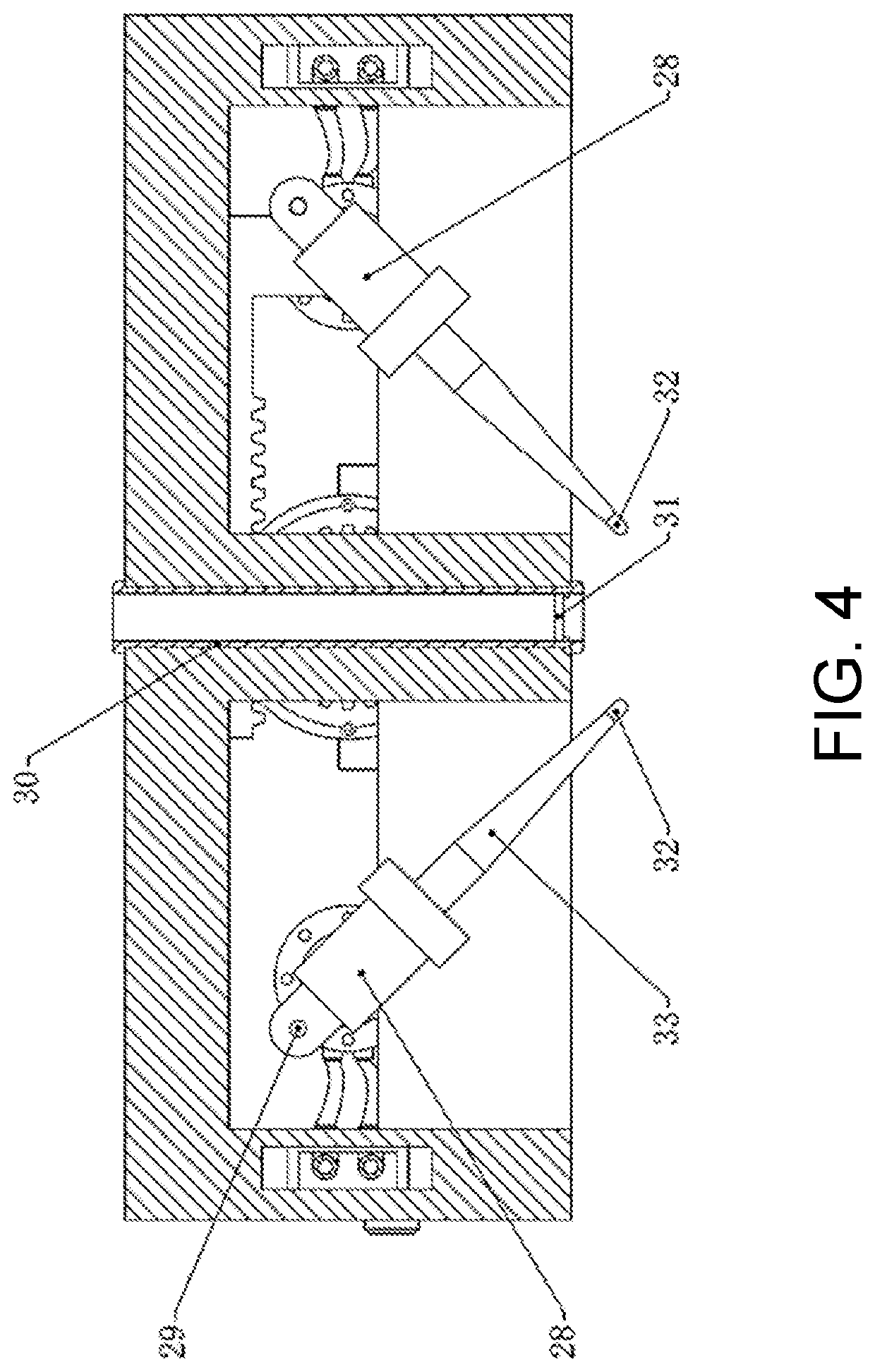
[0079]The initial angle between the shock head 32 and the surface of the workpiece 1 is α1=30°, and the end angle between the shock head 32 and the surface of the workpiece 1 is α3=22°. n=3, that is, the shock head 32 shocks for 3 times between the initial angle and the end angle. An intermediate value is taken, that is, α2=26°. ΔTi is calculated as follows.

[0080]The propagation velocity VU1 of the ultrasonic shock wave in the aluminum alloy workpiece and the transmission piles is approximately 6,320 m / s.

[0081]The propagation velocity VU2 of the ultrasonic shock wave in the stainless steel horn and the shock head is approximately 5,900 m / s.

[0082]The propagation velocity VL of the laser shock wave in the aluminum alloy workpiece is approxi...


PUM

PropertyMeasurementUnit
thicknessaaaaaaaaaa
propagation velocity VU1aaaaaaaaaa
propagation velocityaaaaaaaaaa

Abstract

The present invention provides a device for peening by coupling a laser shock wave and an ultrasonic shock wave in real time. The device includes a synchronization device, a laser device, two ultrasonic shock devices, a working platform and a control system. An upper casing is supported above a base through second hydraulic cylinders. Two supporting beams are provided under the upper casing through the second hydraulic cylinders. Limiting slide rails are provided under the upper casing through first hydraulic cylinders. The two ultrasonic shock devices are connected through the synchronization device, which is configured to synchronize movement and rotation of the two ultrasonic shock devices. The laser device is configured to generate a laser beam to pass through the upper casing and irradiate a surface of a workpiece. The control system controls the laser device to lag behind the two ultrasonic shock devices to perform laser shock.

Description

CROSS-REFERENCE TO RELATED APPLICATION[0001]This application claims the priority benefit of China application serial no. 202110150074.3, filed on Feb. 3, 2021. The entirety of the above-mentioned patent application is hereby incorporated by reference herein and made a part of this specification.BACKGROUNDTechnical Field[0002]The present invention relates to the technical field of laser processing, and in particular to a device and method for peening by coupling a laser shock wave and an ultrasonic shock wave.Description of Related Art[0003]The laser shock technique aims for the surface peening and forming of a metal material through a shock wave generated by the interaction of a nanosecond pulsed laser beam with the material. However, the shock wave induced by the laser beam alone has low amplitude and short time, resulting in a low residual compressive stress and a low degree of grain refinement on the surface of the part, which leads to a poor peening / forming effect and poor contr...

Claims


Application Information

Patent Timeline
Patent Type & Authority Applications(United States)
IPC IPC(8): C21D10/00F01D5/28
CPCC21D10/005G01N2291/0234F01D5/286
Inventor MENG, XIANKAIZHAO, YAOMINLU, JINZHONGZHOU, JIANZHONGZHANG, YANHUHUANG, SHUCAI, JIELI, PENGFEI
Owner JIANGSU UNIV
Why Eureka
Eureka Blog
Learn More