Method of constructing an offshore structure, and offshore structure

a technology of offshore structure and construction method, applied in the direction of vessel construction, special-purpose vessels, passenger handling apparatus, etc., can solve the problems of difficult construction work, high cost of use, and difficulty in proceeding with crane vessel construction

Active Publication Date: 2017-07-13
MODEC
View PDF8 Cites 11 Cited by
  • Summary
  • Abstract
  • Description
  • Claims
  • Application Information

AI Technical Summary

Benefits of technology

[0041]As described above, according to the method of constructing an offshore structure and the offshore structure of the present invention, an offshore structure can be moored safely at an offshore installation site without using a crane vessel in a method of constructing an offshore structure such a spar type with a wind turbine or the like mounted thereon.

Problems solved by technology

When the float is moored, and the tower is hang down to be integrated with the moored float by a crane vessel, the crane vessel, which is expensive for use, is necessary.
Moreover, since the tower hung down by the crane is likely to be affected by winds, which requires control of the swings of the tower and the float.
Accordingly, there is a problem in that the tower installation construction work is difficult to proceed.

Method used


Image

  • Method of constructing an offshore structure, and offshore structure
  • Method of constructing an offshore structure, and offshore structure
  • Method of constructing an offshore structure, and offshore structure

Examples


first embodiment

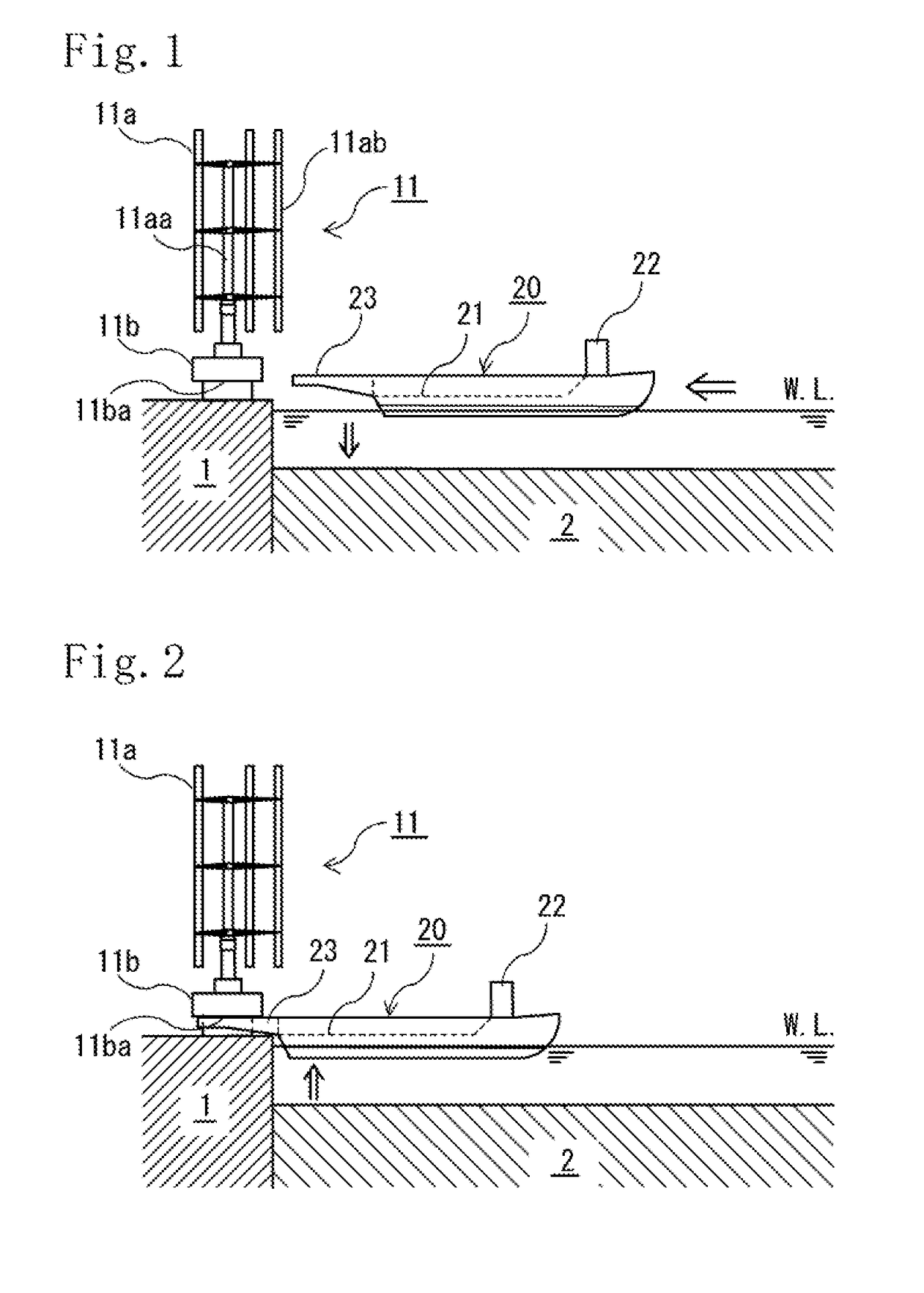
[0071]As illustrated in FIGS. 1 to 15, an offshore structure 10 of a first embodiment illustrated herein is an offshore structure into which an upper structure 11 and a lower structure 12 are joined and which is disposed onshore. The upper structure 11 includes: a vertical-axis wind wheel 11a having a rotary shaft 11aa and a vertical blades 11ab; and a wind-wheel supporting portion lib which supports the vertical-axis wind wheel 11a. In addition, the lower structure 12 includes a vertical axis water wheel.

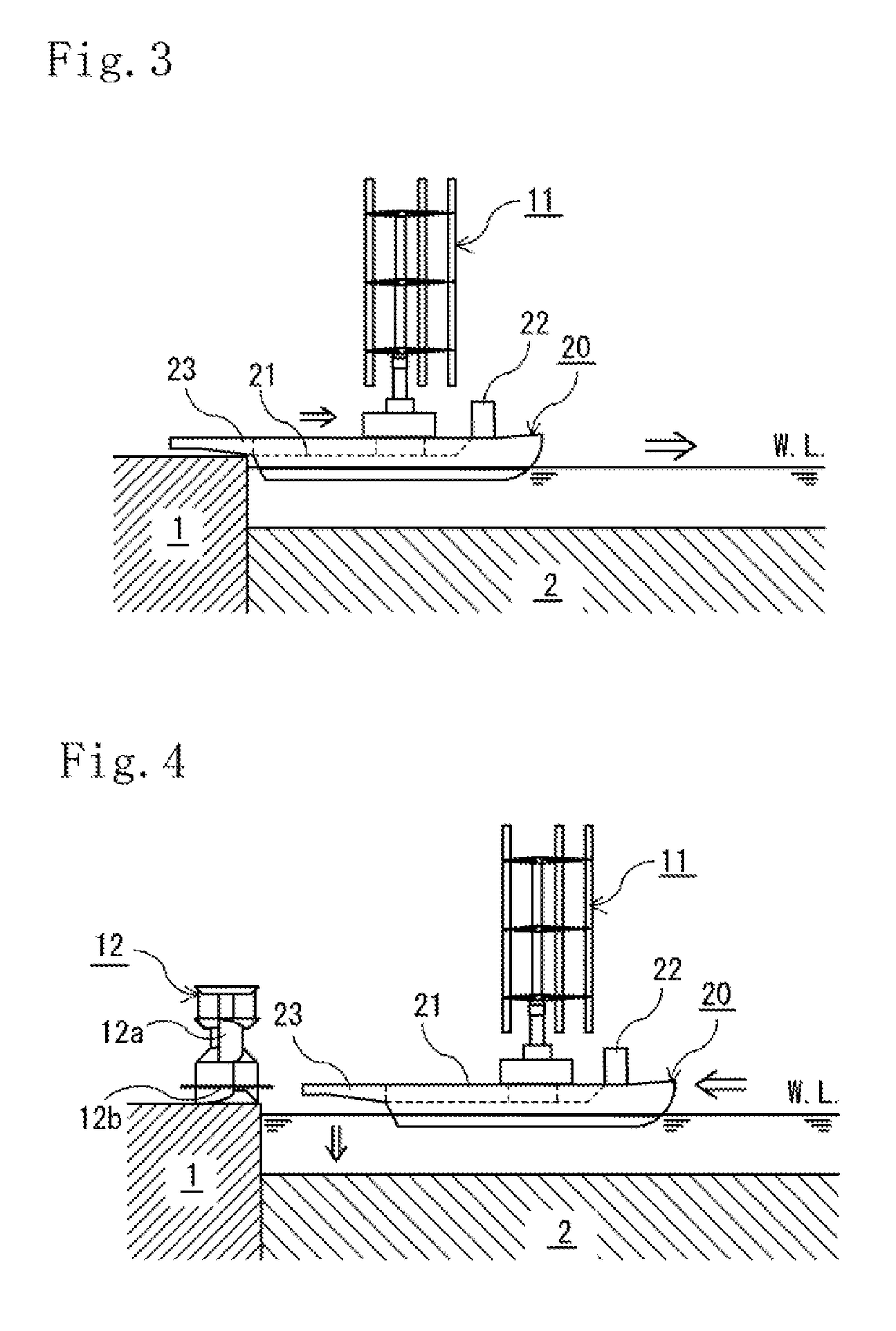
[0072]For the upper structure 11 to be capable of being mounted in an upright standing state on a carrier vessel 20, the wind-wheel supporting portion 11b of the upper structure 11 includes an engagement portion 11ba configured such that while the upper structure 11 is in the upright standing state, the engagement portion 11ba can receive a pair of arm-shaped structures 23 provided to the carrier vessel 20 and sliding thereinto from a lateral side, and be placed onto the pair of ar...

second embodiment

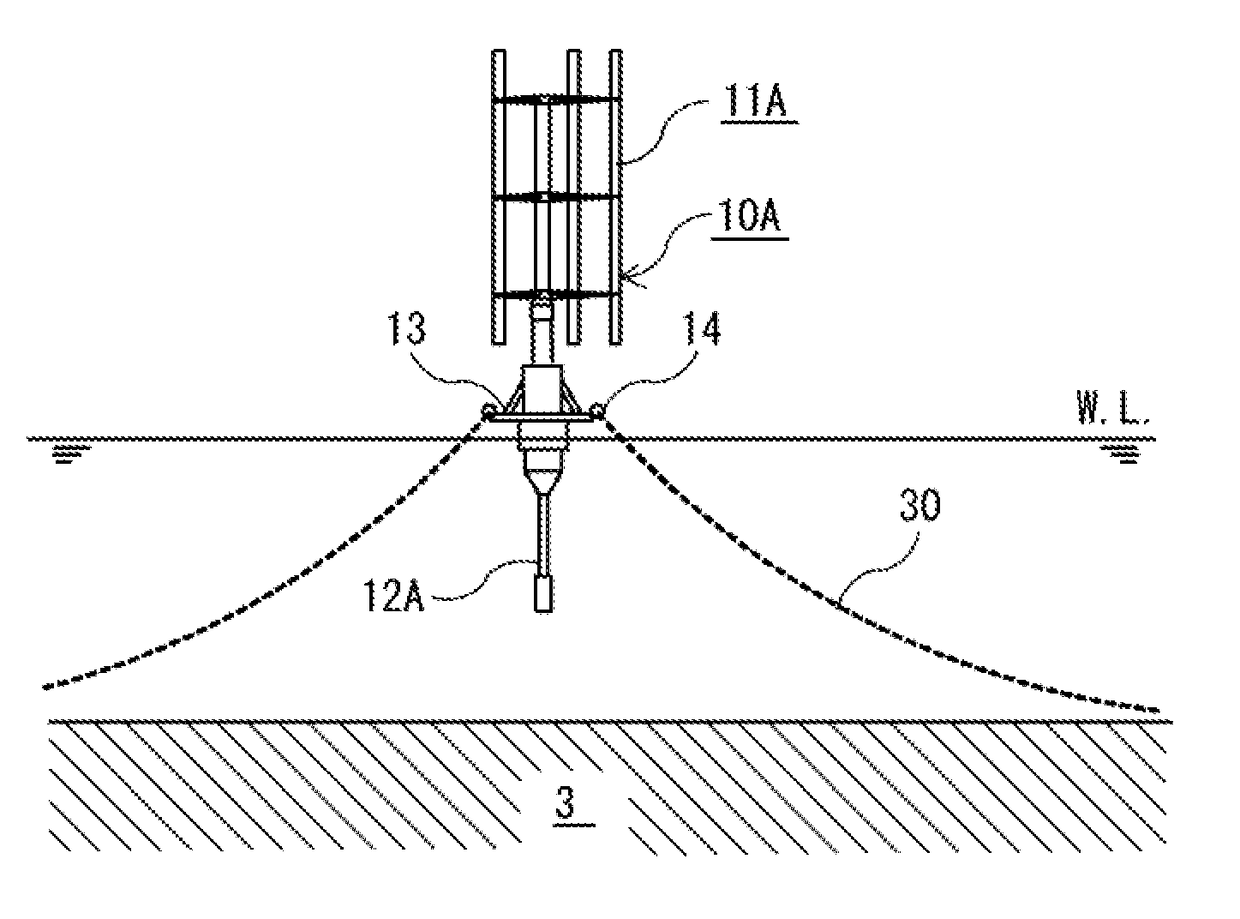
[0073]As illustrated in FIGS. 16 to 24, an offshore structure 10A of a second embodiment is different in that a lower structure 12A does not include the vertical axis water wheel and is formed of a weight. The shape of the offshore structure 10A is more likely to be substantially the same as a known shape as the spar-type offshore structure.

[0074]In addition, as illustrated in FIGS. 1 to 14 and 16 to the carrier vessel 20 includes: a deck 21 on which the upper structure 11 can be mounted in an upright standing state; a bridge 22 for navigation; and propulsion devices such as a propulsion engine and propellers and a fuel tank, which are not illustrated. Moreover, the carrier vessel 20 includes ballast tanks and configured to be capable of loading and discharging ballast water and controlling movement between the ballast tanks to adjust the draft and trim of the hull (inclination in a bow-stern direction) when a heavy-weight carried object is loaded or unloaded and when a carried obje...


PUM


Abstract

An offshore structure is separated into an upper structure and a lower structure. Part or whole of the lower structure is kept in an upright standing state in water. The upper structure is moved to above the lower structure kept in the upright standing state. A uniting step includes one or both of raising the lower structure to arrange the lower structure on a lower side of the upper structure and lowering the upper structure to arrange the upper structure on an upper side of the lower structure by submerging part of a carrier vessel on which the upper structure is mounted while being held by a pair of arm-shaped structures of the carrier vessel and integrating the lower structure with the upper structure. In this way, an offshore structure is moored safely at an offshore installation site without using a crane vessel.

Description

[0001]The present invention relates to a method of constructing a floating structure of a spar-type or the like on which a wind turbine or the like is mounted, and to an offshore structure section.BACKGROUND ART[0002]When a wind turbine is mounted on a floating structure in a sea area having a deep water depth, a semi-submersible type, a tension leg platform (TLP), or the like may possibly be employed. In such cases, the wind turbine or the like and the floating structure are integrally assembled and subjected to test operation onshore, and then towed to an installation site and moored by a mooring system.[0003]On the other hand, in the case of the spar-type, the spar is a floating structure floating in an upright standing state like a fishing float, and a large part of the float is submerged under the sea level by injection of ballast water, or the like. The spar is relatively unlikely to swing, and can support a heavy upper structure. In the case of a spar-type floating structure ...

Claims


Application Information

Patent Timeline
Patent Type & Authority Applications(United States)
IPC IPC(8): B63B35/44B63B27/36B63B21/50B63B27/08B63B22/20B63B21/20
CPCB63B35/44B63B22/20B63B21/20B63B21/502B63B2021/203B63B27/36B63B2035/446B63B2207/02B63B27/08B63B35/00B63B2021/505B63B35/003F03D13/25B63B75/00Y02P70/50F03D9/00Y02E10/727Y02E10/72
Inventor NAKAMURA, TAKUJU
Owner MODEC
Why Eureka
Try Eureka