Eureka AIR delivers breakthrough ideas for toughest innovation challenges, trusted by R&D personnel around the world.

Method and System for Adjusting Light Pattern for Structured Light Imaging

a structured light and light pattern technology, applied in the field of structured light, can solve the problems of low spatial resolution, fixed pattern lack of flexibility to respond to different scene conditions, combination of constructive and destructive interference, etc., and achieve the effects of long scene acquisition time, low energetic efficiency, and lack of flexibility

Active Publication Date: 2017-07-13
META PLATFORMS TECH LLC
View PDF3 Cites 8 Cited by
  • Summary
  • Abstract
  • Description
  • Claims
  • Application Information

AI Technical Summary

Benefits of technology

The present invention addresses the limitations of fixed patterned light and temporal coding, which include lack of flexibility and low energy efficiency, as well as longer acquisition time for the scene. The technical effects of this invention include increased flexibility, higher energy efficiency, and faster acquisition time for the scene.

Problems solved by technology

This method is efficient in terms of projected pattern power use and acquisition time, but requires dedication of several pixels to each label and hence results in lower spatial resolution.
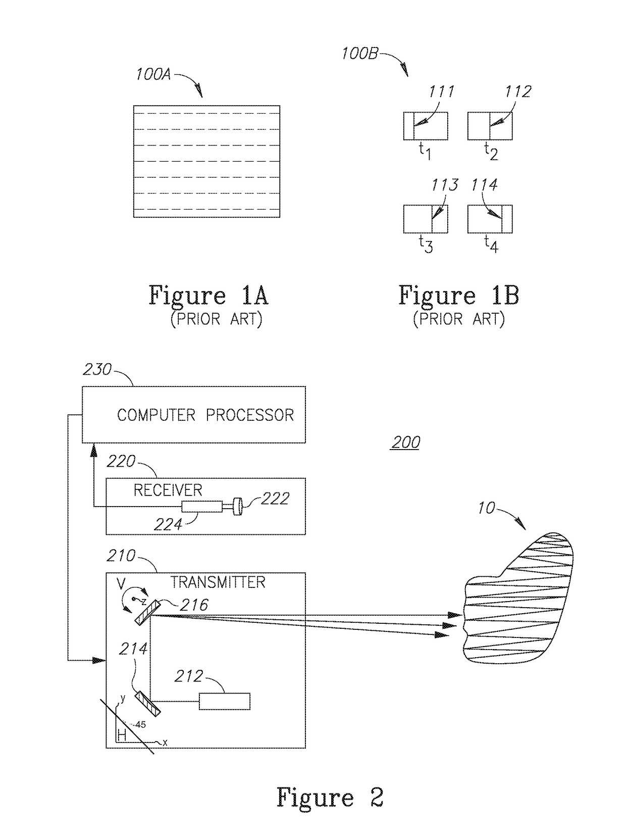
The main disadvantage is that a fixed pattern lacks the flexibility to respond to different scene conditions by using a different pattern. FIG. 1A illustrates a fixed light pattern 100A exhibiting broken lines according to the prior art.
The fixed pattern may be implemented using a mask of phase shifters configured to result in combination of constructive and destructive interferences.
The method can be accurate and has flexibility, but is not power efficient and requires a long acquisition time. FIG. 1B illustrates a temporal light pattern 100B according to the prior art, exhibiting a unique vertical line 111, 112, 113, and 114 for each of time stamps t1, t2, t3, and t4 respectively.
While the ability to dynamically change the pattern is highly desired, the power inefficiency it ensued makes it very unattractive in many applications.
Considering the maximal output of the light source, its modulation reduces the “on” time and hence reduces the total output power.
When the light is modulated in order to produce the desired pattern, the average intensity is reduced by the modulation and hence a loss of brightness results.

Method used


Image

  • Method and System for Adjusting Light Pattern for Structured Light Imaging
  • Method and System for Adjusting Light Pattern for Structured Light Imaging
  • Method and System for Adjusting Light Pattern for Structured Light Imaging

Examples


Embodiment Construction

[0023]With specific reference now to the drawings in detail, it is stressed that the particulars shown are by way of example and for purposes of illustrative discussion of the preferred embodiments of the present technique only, and are presented in the cause of providing what is believed to be the most useful and readily understood description of the principles and conceptual aspects of the present technique. In this regard, no attempt is made to show structural details of the present technique in more detail than is necessary for a fundamental understanding of the present technique, the description taken with the drawings making apparent to those skilled in the art how the several forms of the invention may be embodied in practice.

[0024]Before explaining at least one embodiment of the present technique in detail, it is to be understood that the invention is not limited in its application to the details of construction and the arrangement of the components set forth in the followin...


PUM


Abstract

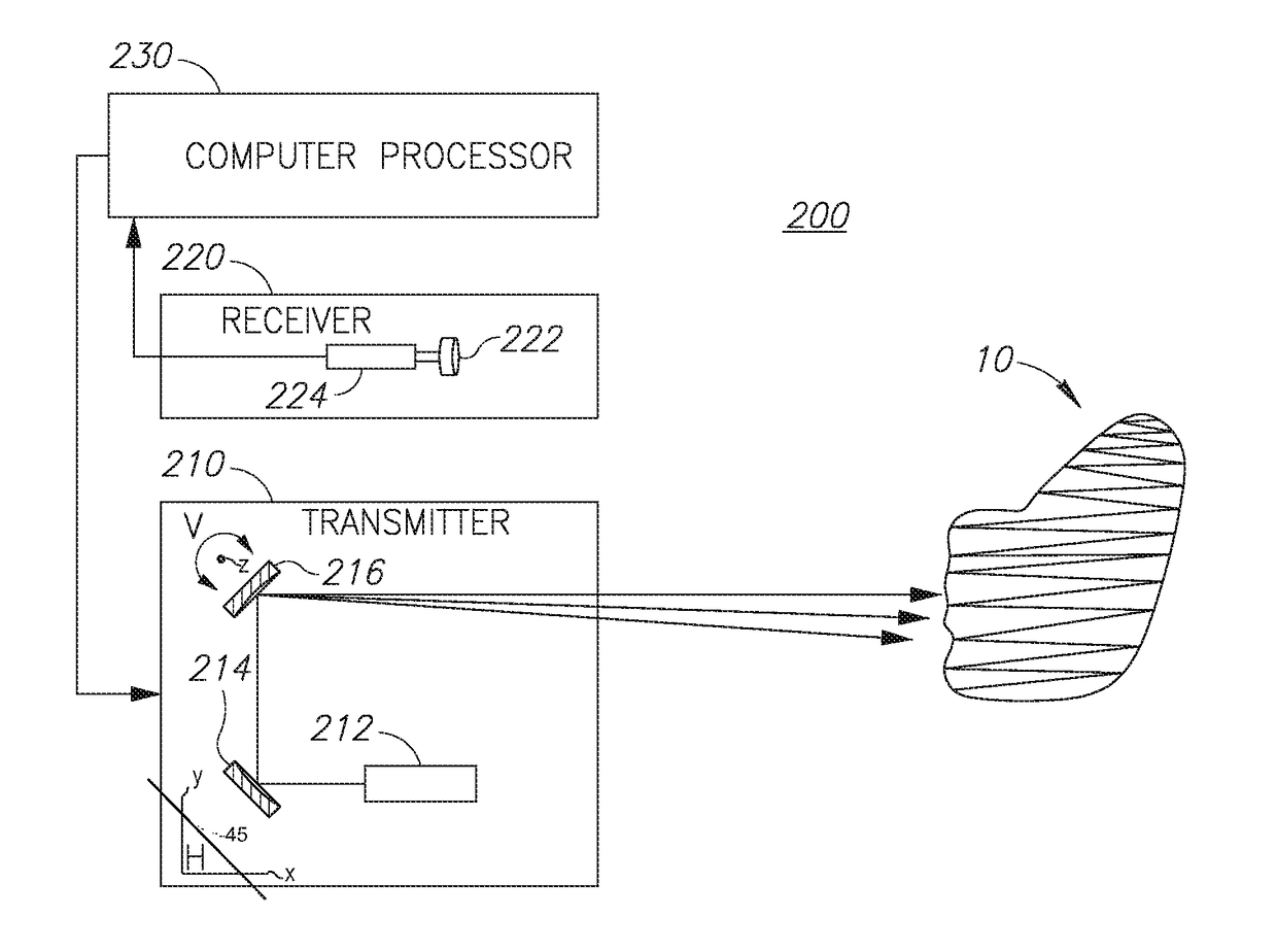
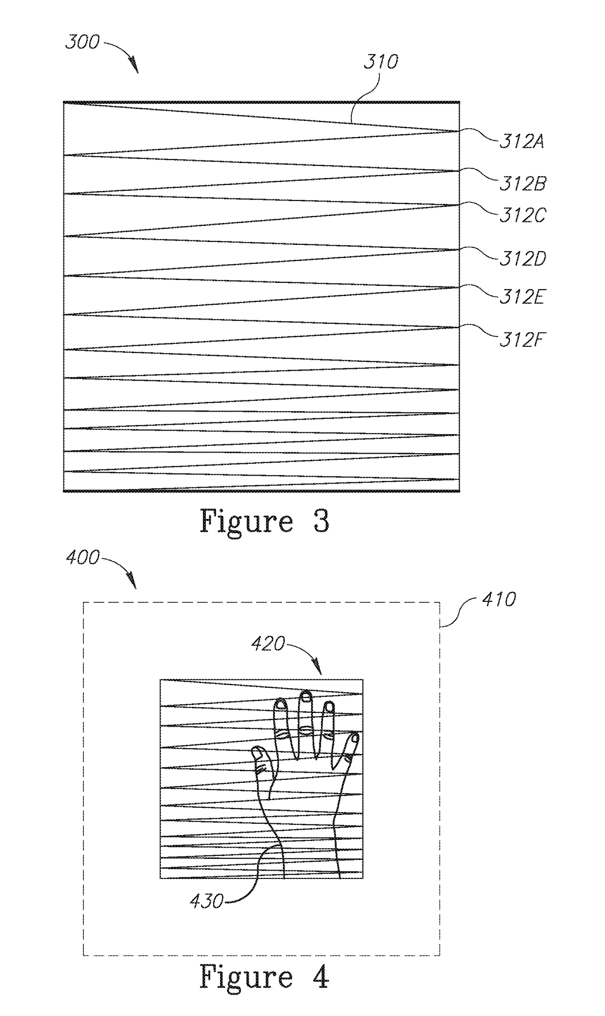
A system and a method for producing an adjustable light pattern are provided herein. The system may include: a transmitter configured to illuminate a scene with a patterned light being adjusted based on predefined criteria; a receiver configured to receive reflections of the adjusted patterned light; and a computer processor configured to control the adjustment of the patterned light and further analyze the received reflections, to yield a depth map of objects within the scene, wherein the transmitter may include: a light source configured to produce a light beam; a first reflector tiltable approximately along a line on an x-y plane in a Cartesian x-y-z coordinate system; and a second reflector tiltable along a z-axis in said coordinate system, wherein the reflectors are tilted along their respective axes back and forth so as to divert the light beam for creating the adjusted patterned light.

Description

TECHNICAL FIELD[0001]The present invention relates generally to structured light, and more particularly, to adjusting light pattern in a structured light system.BACKGROUND OF THE INVENTION[0002]Prior to setting forth the background of the invention, it may be helpful to set forth definitions of certain terms that will be used hereinafter.[0003]The term “structured light” as used herein is defined as the process of projecting a known pattern of pixels (e.g. grids or horizontal bars) on to a scene. The projected patterned light is deformed when striking surfaces and analyzing the deformation allows vision systems to calculate the depth and surface information of the objects in the scene. For providing further details of how structured light can be implemented, by way of illustration only, WIPO publication number WO2013088442 is incorporated herein by reference in its entirety.[0004]The term “spatial coding” as used herein is defined as a fixed pattern that is projected onto the scene ...

Claims


Application Information

Patent Timeline
IPC IPC(8): G01B11/25G01B11/22G06T7/521G01S17/89
CPCG01B11/2513G01S17/89G06T2207/10028G06T7/521G01B11/22G01B11/2518G01B11/25G02B27/42G01S17/894
Inventor RAZ, GUY
Owner META PLATFORMS TECH LLC
Why Eureka
Eureka Blog
Learn More