Deformation detection method for a sealed-type rechargeable battery and sealed-type rechargeable battery

Inactive Publication Date: 2017-07-13
TOYO TIRE & RUBBER CO LTD
View PDF2 Cites 1 Cited by
  • Summary
  • Abstract
  • Description
  • Claims
  • Application Information

AI Technical Summary

Benefits of technology

The patent describes a method for detecting deformation of a rechargeable battery using a polymer matrix layer. The layer deforms when the battery swells due to cell expansion, and the change in external field caused by this deformation is detected. This allows for sensitive detection of battery deformation with accuracy. The method is also adaptable to detecting electrode swelling or gas swelling, making it easy to distinguish between the two. Additionally, the method allows for the detection to be made with high precision by distinguishing between electrode swelling and gas swelling. The polymer matrix layer can be attached to the outer surface of the battery's outer casing or the electrode group, and the detection unit can be fewer than the number of polymer matrix layers, resulting in space savings or weight reduction.

Problems solved by technology

the rechargeable battery has a problem that, when the electrolytic solution is decomposed due to overcharging or the like, the cell swells to be deformed in accordance with rise in the internal pressure caused by the decomposition gas and, unless the charging current or the discharging current is stopped, this results in rupture of the rechargeable battery.
However, the sensitivity region of such a strain gauge is comparatively narrow.
Therefore, it seems impossible to detect with a high precision by distinguishing between these swellings with the strain gauge.
However, in this method, the swelling of the thin-type batteries is not directly detected, thereby raising a fear that the sensitivity may be insufficient in detecting deformation of the rechargeable battery caused by swelling of the cells.
However, in order to detect these inter-axial distances, a plurality of piezoelectric elements must be provided for one cell case, thereby unavoidably making the structure complex.

Method used


Image

  • Deformation detection method for a sealed-type rechargeable battery and sealed-type rechargeable battery
  • Deformation detection method for a sealed-type rechargeable battery and sealed-type rechargeable battery
  • Deformation detection method for a sealed-type rechargeable battery and sealed-type rechargeable battery

Examples


first embodiment

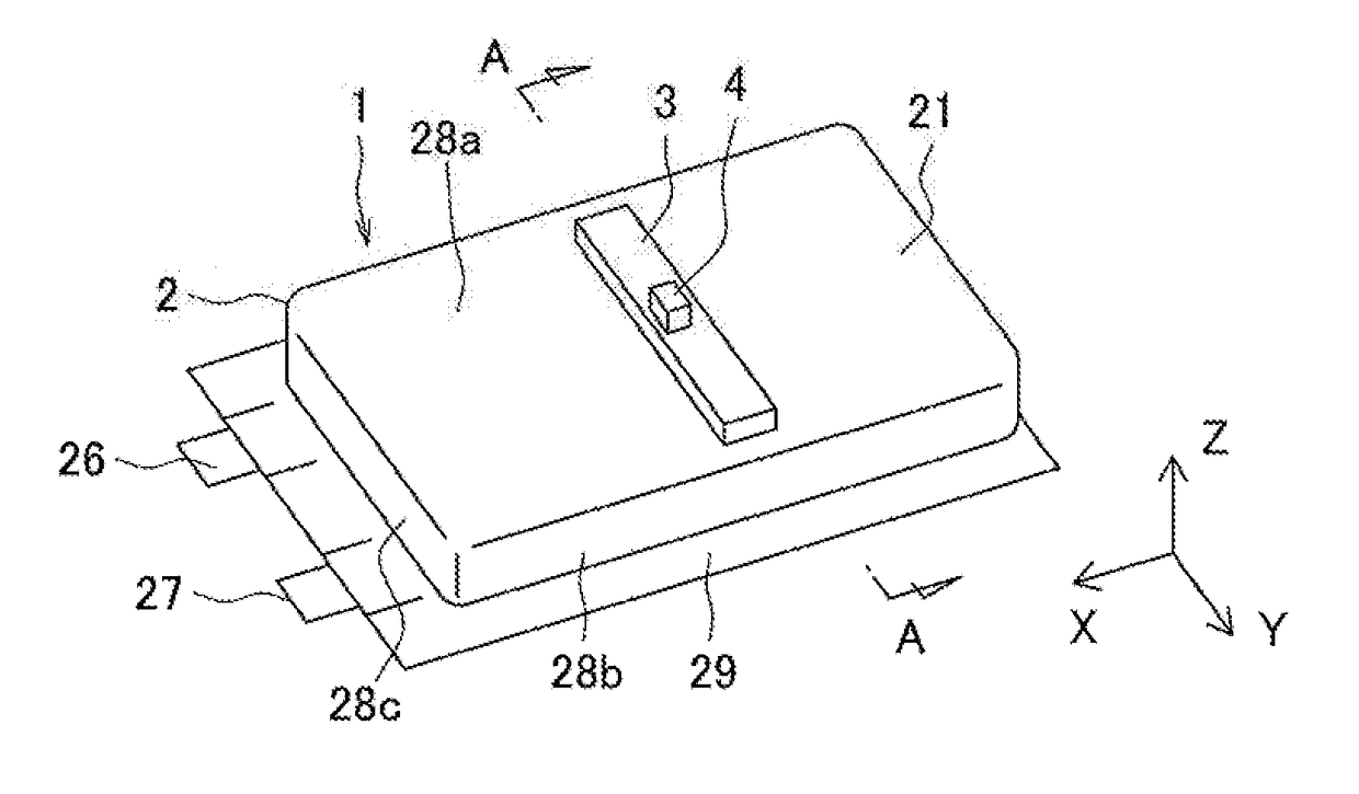
[0037]The sealed-type rechargeable battery 1 shown in FIG. 1 is provided with a polymer matrix layer 3 and a detection unit 4. A cell 2 constituting this rechargeable battery 1 has a structure in which an electrode group 22 is accommodated in a sealed outer casing 21. The electrode group 22 in the present embodiment is formed by stacking a positive electrode 23 and a negative electrode 24 with a separator 25 interposed therebetween, and such a stacked body is enclosed in the outer casing 21 together with an electrolytic solution. Leading wires are respectively connected to the positive electrode 23 and the negative electrode 24, and terminal ends of these leading wires protrude to the outside of the outer casing 21, so as to construct electrode terminals 26 and 27. The electrode terminals 26 and 27 are provided at one end in the X-direction of the outer casing 21.

[0038]The rechargeable battery 1 of the present embodiment is a laminate battery using a laminate film such as an aluminu...

second embodiment

[0062]A second embodiment has a construction and a function similar to those of the first embodiment except for the matters described below, so that mainly the differing points will be described by omitting description of the common points. Here, constituent elements equal to the constituent elements already described will be denoted with equal reference signs, and duplicated description thereof will be omitted. The same applies to the third to eighth embodiments described later as well.

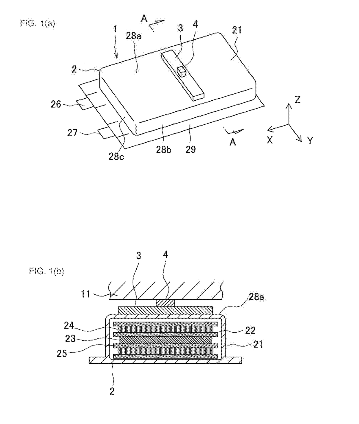
[0063]Referring to FIG. 2, in the present embodiment, a polymer matrix layer 3 is attached to an outer surface of a wall portion 28b of an outer casing 21 that faces an electrode group 22 in a direction perpendicular to the thickness direction of a positive electrode 23 and a negative electrode 24, specifically, in the Y-direction (right-and-left direction in FIG. 2b). The outer surface of the wall portion 28b corresponds to a side surface of the outer casing 21. The polymer matrix layer 3 faces the ...

third embodiment

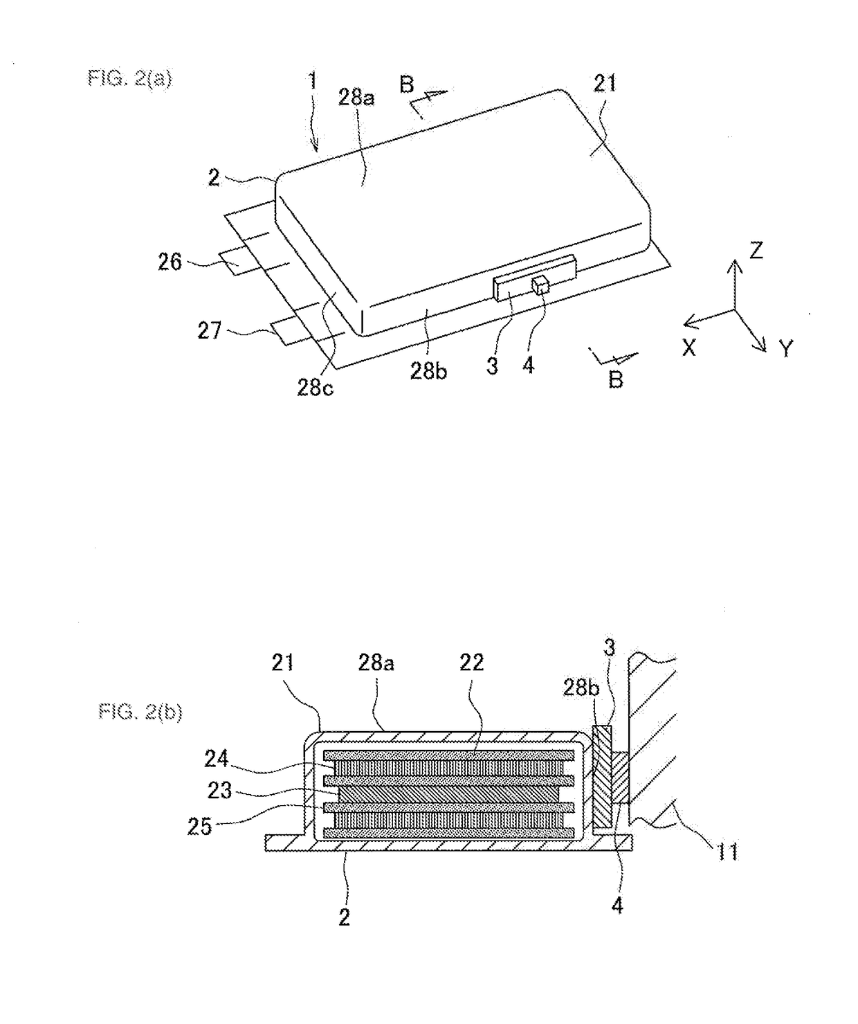
[0064]Referring to FIG. 3, in the present embodiment, a polymer matrix layer 3 is attached to an outer surface of a wall portion 28c of an outer casing 21 that faces an electrode group 22 in a direction perpendicular to the thickness direction of a positive electrode 23 and a negative electrode 24, specifically, in the X-direction (right-and-left direction in FIG. 3b). The outer surface of the wall portion 28c corresponds to a side surface of the outer casing 21. The polymer matrix layer 3 faces the electrode group 22 with the wall portion 28c interposed therebetween, and is disposed perpendicularly to an upper surface of the electrode group 22. The detection unit 4 is attached to an inner surface of a case (not shown) of a battery module that faces the wall portion 28c. The electrode swelling exerts a larger action in the Z-direction. Therefore, in the present embodiment in which the polymer matrix layer 3 is attached to the wall portion 28c, the electrode swelling is hardly reflec...


PUM


Abstract

In a deformation detection method for a sealed-type rechargeable battery 1 in which an electrode group 22, which is formed by stacking a positive electrode 23 and a negative electrode 24 with a separator 25 interposed therebetween, is accommodated in a sealed outer casing 21, a polymer matrix layer 3 is attached to an outer surface of a wall portion 28a of the outer casing 21 that faces the electrode group 22 in a thickness direction of the positive electrode 23 and the negative electrode 24 or in a direction perpendicular to the thickness direction. The polymer matrix layer 3 contains a filler that is dispersed therein and that changes an external field in response to deformation of the polymer matrix layer 3. Change in the external field accompanying the deformation of the polymer matrix layer 3 is detected by a detection unit 4.

Description

TECHNICAL FIELD[0001]The present invention relates to a deformation detection method for a sealed-type rechargeable battery in which an electrode group is accommodated in a sealed outer casing as well as to the sealed-type rechargeable battery.BACKGROUND ART[0002]In recent years, a sealed-type rechargeable battery (which may be hereinafter simply referred to as “rechargeable battery”) represented by a lithium ion rechargeable battery is used as a power source not only for a mobile apparatus such as a portable phone or a notebook personal computer but also for an electrically driven vehicle such as an electric automobile or a hybrid car. A cell constituting the rechargeable battery has a structure in which an electrode group is accommodated in an inside of a sealed outer casing, and the electrode group is constructed by winding or stacking a positive electrode and a negative electrode with a separator interposed therebetween. For example, a laminate film such as an aluminum laminate ...

Claims


Application Information

Patent Timeline
IPC IPC(8): H01M10/48H01M10/0587H01M10/0525G01B7/24H01M50/119H01M50/121H01M50/124
CPCH01M10/48H01M10/0525H01M10/0587G01B7/24H01M10/0585Y02E60/10Y02P70/50H01M50/121H01M50/124H01M50/119G01R31/36H01M10/34Y02T10/70
Inventor FUKUDA, TAKESHIMINAKATA, NOBUYUKI
Owner TOYO TIRE & RUBBER CO LTD
Why Eureka
Try Eureka