
Polymer Flooding Processes for Viscous Oil Recovery in Carbonate Reservoirs

Active Publication Date: 2017-07-20
SAUDI ARABIAN OIL CO
View PDF4 Cites 8 Cited by
  • Summary
  • Abstract
  • Description
  • Claims
  • Application Information

AI Technical Summary

Benefits of technology

The patent relates to a method for improving the production of oil from carbonate reservoir formations. The method involves injecting a smart water / polymer slug into the formation to alter its wettability and make it more suitable for oil production. The smart water has a specific volume and is viscous. The method may also include injecting tapered plugs into the reservoir formation. The technique is effective in viscous oil reservoirs and can help increase oil production from carbonate reservoirs.

Problems solved by technology

The divalent cations are much more detrimental when compared to monovalent cations due to their strong bridging effect with polymer chain and they can precipitate polymer from solution even at relatively lower ionic concentrations.
Therefore, the use of high salinity water is typically limited to situations in which the availability of high salinity water, such as seawater, is readily available.
Such requirements of high polymer dosage can become cost prohibitive to apply polymer flooding technology in certain formations containing viscous crude oils.

Method used


Image

  • Polymer Flooding Processes for Viscous Oil Recovery in Carbonate Reservoirs
  • Polymer Flooding Processes for Viscous Oil Recovery in Carbonate Reservoirs

Examples


example 1

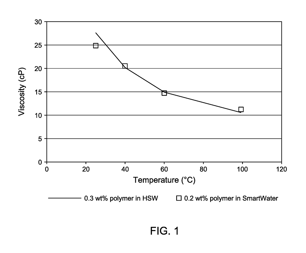
[0049]Example 1 is a comparison study of rheology data on a high salinity water (HSW) / polymer composition and a smart water / polymer composition conducted at different temperatures. A copolymer of acrylamide and ATBS was used as the polymer. The copolymer of acrylamide and ATBS was a sulfonated polyacrylamide, AN-125, from SNF Floerger, France. The copolymer of acyrlamide and ATBS had a molecular weight of 12 million Dalton, a polyacrylamide hydrolysis degree of 5%, and contained a polymer content of 25% ATBS and 75% acrylamide. The HSW was prepared to have a TDS of about 69,000 ppm containing 55,786 mg / L of NaCl; 10,654 mg / L of CaCl2.2H2O; 4,483 mg / L of MgCl2.6H2O; 2,610 mg / L of Na2SO4; and 503.9 mg / L NaHCO3. The smart water was prepared to have a TDS of about 6,900 ppm, making it a 10-times diluted version of the HSW containing 5,578.6 mg / L of NaCl; 1,065.4 mg / L of CaCl2.2H2O; 448.3 mg / L of MgCl2.6H2O; 261 mg / L of Na2SO4; and 50.39 mg / L NaHCO3.

[0050]The HSW / polymer composition and ...

example 2

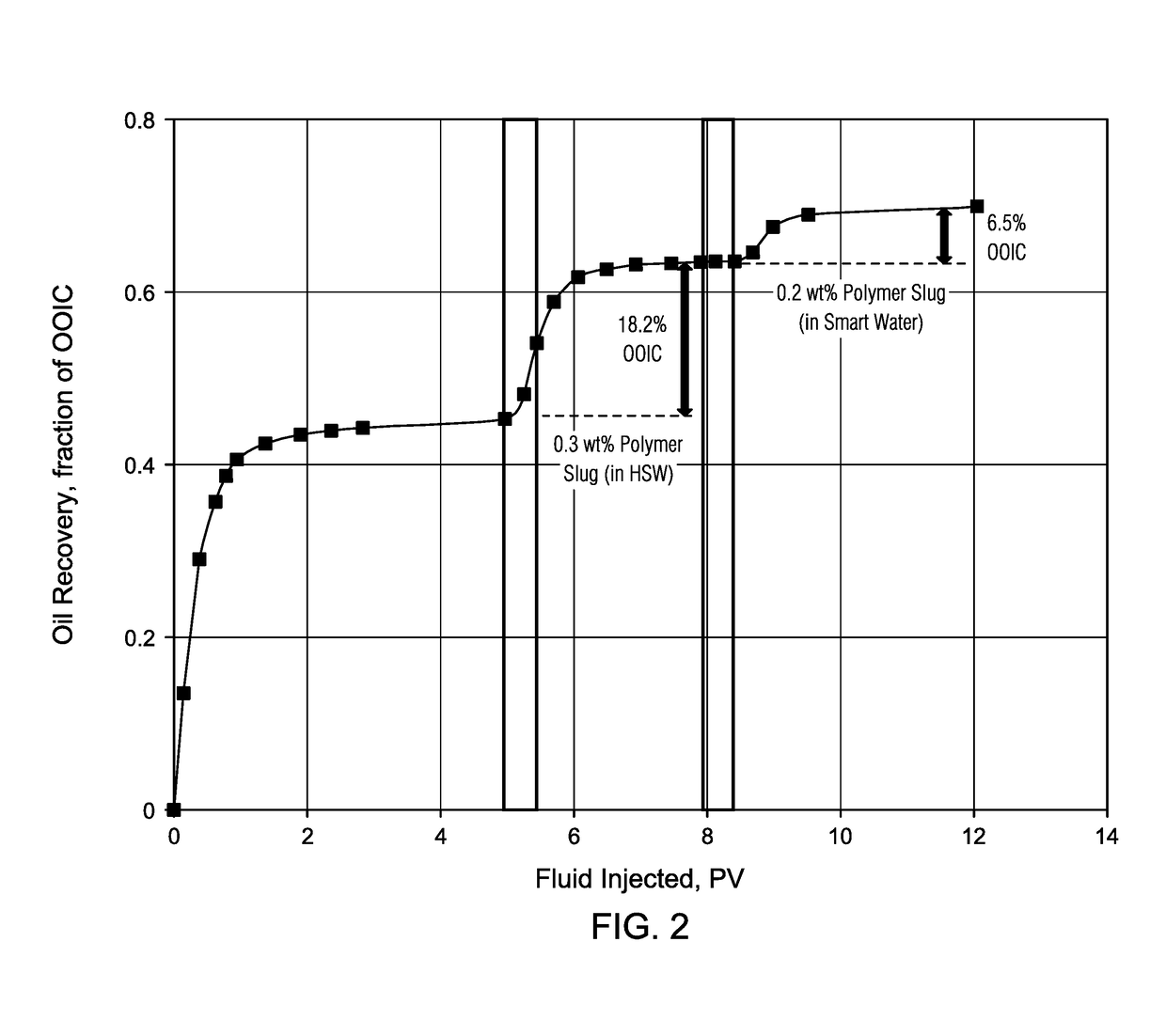
[0053]Example 2 describes a reservoir condition core flood study using the same HSW and smart water compositions of Example 1. A carbonate reservoir core sample having a permeability of 2.0 Darcy was fully saturated with brine first and then a viscous crude oil having a viscosity of 4.5 cP was injected into the core to establish initial water saturation. The carbonate reservoir core sample was then submerged in the viscous crude oil and aged for four weeks. After four weeks, the carbonate reservoir core sample was loaded into a coreflooding system and then the oil displacement tests were conducted at reservoir conditions.

[0054]In a first step of the oil displacement tests, oil was displaced by the injection of a high salinity water, in the absence of polymer with a composition as described in Example 1. In a second step, a HSW / polymer slug of 0.3 wt % polymer in HSW was injected. Finally, a smart water / polymer slug of 0.2 wt % polymer in smart water was injected. The oil recovery da...


PUM


Abstract

A composition for use in a polymer flooding operation in a viscous oil containing carbonate reservoir formation with in situ rock is provided. The composition includes a polymer, the polymer operable to increase the viscosity of the composition; and a smart water, the smart water operable to alter a wettability of the in situ rock, wherein the smart water has a total dissolved solids of between 5,000 ppm and 7,000 ppm, wherein the total dissolved solids comprises one or more salts; wherein the composition has a viscosity between 4 cP and 100 cP.

Description

CROSS-REFERENCE TO RELATED APPLICATION[0001]This application claims priority from U.S. Provisional Application No. 62 / 280,446, filed Jan. 19, 2016, and titled “IMPROVED OIL RECOVERY PROCESS USING AN OIL RECOVERY COMPOSITION OF SMART WATER AND DILUTE POLYMER FOR CARBONATE RESERVOIRS.” For purposes of United States patent practice, this application incorporates the contents of the Provisional Application by reference in its entirety.BACKGROUND OF THE INVENTION[0002]Field of the Invention[0003]This invention relates to methods and compositions for polymer flooding operations. More specifically, the invention relates to methods and compositions using smart water and polymers for polymer flooding operations in carbonate reservoirs.[0004]Description of the Related Art[0005]Polymer flooding processes are one of the matured enhanced oil recovery (EOR) technologies and are currently gaining some importance for viscous oil recovery in carbonate reservoirs. Increased aqueous phase viscosities ...

Claims


Application Information

Patent Timeline
IPC IPC(8): C09K8/588E21B43/20C08K3/00
CPCC09K8/588E21B43/20C08K3/00
Inventor AYIRALA, SUBHASH CHANDRABOSEAL-SOFI, ABDULKAREEM M.AL-YOUSEF, ALI ABDALLAHWANG, JINXUN
Owner SAUDI ARABIAN OIL CO
Learn More