Outlet guide vane for aircraft turbine engine, presenting an improved lubricant cooling function

Active Publication Date: 2017-07-20
SN DETUDE & DE CONSTR DE MOTEURS DAVIATION S N E C M A
View PDF4 Cites 19 Cited by
  • Summary
  • Abstract
  • Description
  • Claims
  • Application Information

AI Technical Summary

Benefits of technology

[0016]Besides, the first inner duct may present at least a first zone and a second zone offset from the first zone in the transverse direction, the second zone with an average height between the pressure side and suction side that is lower than the average height of the first zone, and said first zone having an average fin density greater than that of the second zone. This special design allows advantageously to get a more or less homogeneous lubricant flow in the transverse direction of the first inner duct, despite its evolutionary height along this same direction.
[0017]Moreover, said first duct may define a lubricant thawing channel spreading according to the first main direction, said channel being devoid of fins all along

Problems solved by technology

However, the solutions proposed in

Method used


Image

  • Outlet guide vane for aircraft turbine engine, presenting an improved lubricant cooling function
  • Outlet guide vane for aircraft turbine engine, presenting an improved lubricant cooling function
  • Outlet guide vane for aircraft turbine engine, presenting an improved lubricant cooling function

Examples


Embodiment Construction

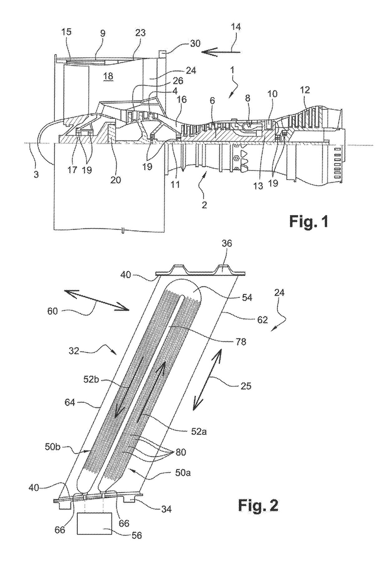
[0037]With reference to FIG. 1, it represents a dual-flow and a dual-body turbojet 1, with a high dilution rate. The turbojet 1 is classically comprised of a gas generator 2 on either sides of which are arranged a low pressure compressor 4 and one low pressure turbine 12, this gas generator 2 comprising a high pressure compressor 6, a combustion chamber 8 and a high pressure turbine 10. Subsequently, the terms “front” and “back” are considered according to an opposite direction 14 to the main flow direction of the gases within the turbojet, this direction 14 being parallel to its longitudinal axis 3. However, the terms “upstream” and “downstream” are considered according to the main flow direction of the gas within the turbojet.

[0038]The low pressure compressor 4 and the low pressure turbine 12 form a low pressure body, and are connected to each other by a low-pressure shaft 11 centred on the axis 3. Similarly, the high pressure compressor 6 and the high-pressure turbine 10 form a h...


PUM


Abstract

The invention relates to a guide vane (24) for a dual flow aircraft turbine engine, the aerodynamic part (32) of the vane comprising an inner duct (50a) for lubricant cooling extending in a main direction (52a) and being partly bounded by a pressure side wall (70) and a suction side wall (72) of the vane.
According to the invention, the aerodynamic part (32) of the vane is embodied from as a single piece, including also the heat transfer fins (80), arranged in the duct (50a) expanding substantially parallel to the direction (52a), the fins (80) being spaced from each other depending on the direction (52a) as well as a transversal direction (60) of the vane, so that at least some of the fins (80) are arranged substantially staggered.

Description

TECHNICAL FIELD[0001]This invention relates to the aircraft dual flow turbine engines field, and in particular the design of guide vanes arranged in the entirety or part of an air flow from a turbine engine fan.[0002]This pertains preferably to outlet guide vanes, also known as OGV, designed to straighten the airflow at the fan outlet. Alternatively or simultaneously, if necessary, guide vanes could be placed at the fan inlet. The guide vanes are classically arranged in the turbine engine secondary vein.[0003]The invention preferably pertains to an aircraft turbojet equipped with such outlet guide vanes.PRIOR STATE OF THE ART[0004]On some dual-flow turbojets, there have been instances where the outlet guide vanes are implemented downstream of the fan to straighten the flow coming out of it, and also eventually to provide a structural function. This last function is indeed intended to allow the passage of efforts from the centre of the turbine engine to an outer ring located in the e...

Claims


Application Information

Patent Timeline
IPC IPC(8): F04D29/58F04D29/54F04D29/063F02K3/06F04D19/00
CPCF04D29/5853F02K3/06F04D19/002F04D29/063F05D2230/30F05D2220/323F05D2240/12F05D2260/22141F04D29/542F01D9/065F02C7/14F05D2220/36F28D2021/0089F28D2021/0021F28D1/0206F28D1/035F28F2250/02Y02T50/60F01D5/18F01D9/041F01D25/12F01D25/20
Inventor ZACCARDI, CEDRICBOUTALEB, MOHAMED-LAMINECHALAUD, SEBASTIEN CHRISTOPHELEMARECHAL, ERIC PIERRE GEORGESPAPIN, THIERRY GEORGES PAUL
Owner SN DETUDE & DE CONSTR DE MOTEURS DAVIATION S N E C M A
Why Eureka
Try Eureka