Method of compensating for an excimer laser annealing mura and display device employing the same

a technology of excimer laser and compensating method, which is applied in the field of display devices, can solve the problem that the conventional ela mura compensating method cannot accurately compensate for the ela mura that exists in the display panel, and achieve the effect of high gray-scale luminan

Active Publication Date: 2017-07-20
SAMSUNG DISPLAY CO LTD
View PDF3 Cites 31 Cited by
  • Summary
  • Abstract
  • Description
  • Claims
  • Application Information

AI Technical Summary

Benefits of technology

[0005]A method of compensating for Mura in a display panel includes displaying a high gray-scale image and a low gray-scale image on a display panel. The high gray-scale image and the low gray-scale image are photographed using a luminance measuring equipment to generate a high gray-scale luminance image and a low gray-scale luminance image, respectively. An ELA Mura for-measurement image having moire-removed luminance values is generated by dividing luminance values of the low gray-scale luminance image by luminance values of the high gray-scale luminance image. One-dimensional average data is obtained, at predetermined rotation angles while rotating the ELA Mura for-measurement image, by sequentially listing average luminance values, each of which is calculated by averaging luminance values in a predetermined direction on the ELA Mura for-measurement image. The obtained one-dimensional average data is transformed into frequency-domain data using a Fast Fourier Transform algorithm. Target frequency-domain data having a maximum peak value is identified from among the frequency-domain data. A direction, an intensity, and a frequency of the ELA Mura are obtained from the target frequency-domain data. An ELA Mura for-compensation band-reject filter is determined based on the obtained direction, intensity, and frequency of the ELA Mura. The ELA Mura for-compensation band-reject filter is applied to initial image data to generate corrected image data.

Problems solved by technology

Since a direction and an intensity of the ELA Mura cannot be accurately measured by an interference phenomenon between a cycle of the ELA and a cycle of the pixels, a conventional ELA Mura compensating method cannot accurately compensate for the ELA Mura that exists in the display panel.

Method used


Image

  • Method of compensating for an excimer laser annealing mura and display device employing the same
  • Method of compensating for an excimer laser annealing mura and display device employing the same
  • Method of compensating for an excimer laser annealing mura and display device employing the same

Examples


Embodiment Construction

[0026]Hereinafter, the present invention will be explained in detail with reference to the accompanying drawings.

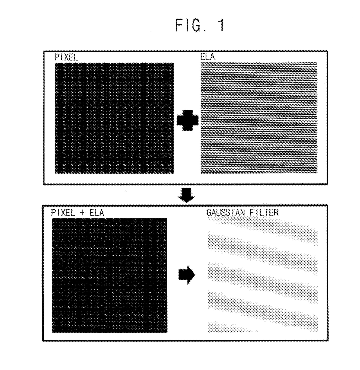
[0027]FIG. 1 is a diagram illustrating an interference phenomenon between a cycle of an ELA

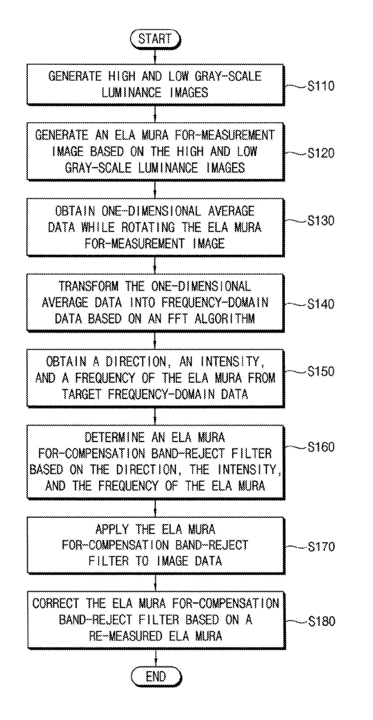
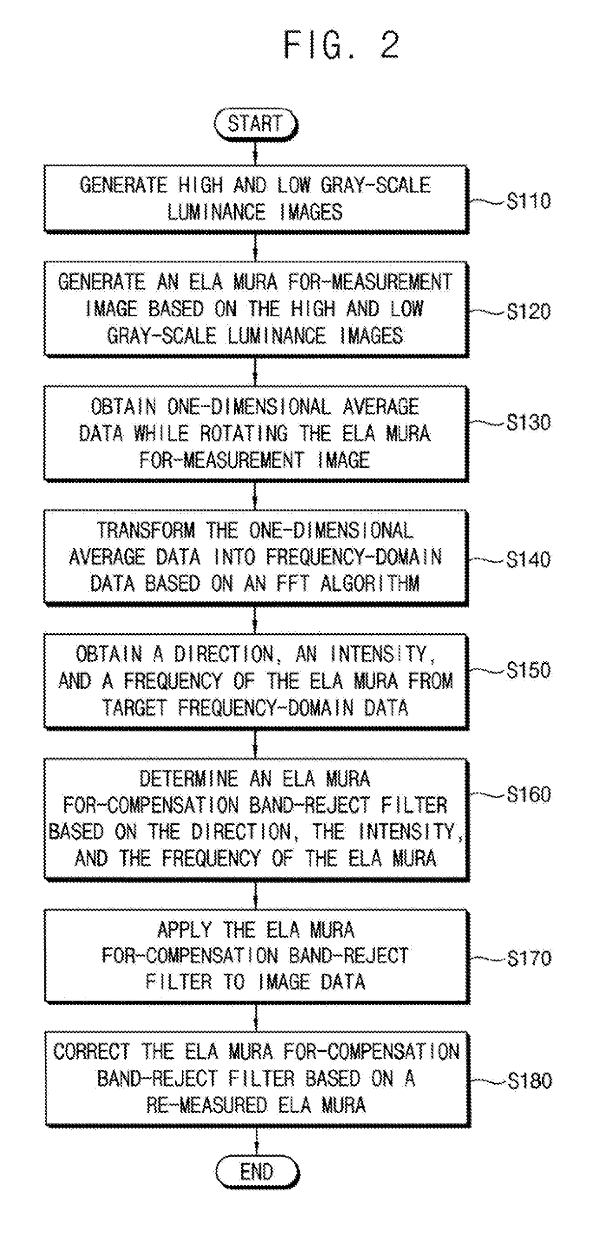
[0028]Mura and a cycle of pixels caused in a display device. FIG. 2 is a flowchart illustrating a method of compensating for an ELA Mura according to exemplary embodiments of the present inventive concept.

[0029]Referring to FIGS. 1 and 2, the method of FIG. 2 may generate a high gray-scale luminance image and a low gray-scale luminance image by photographing a high gray-scale image and a low gray-scale image that are displayed on a display panel using a luminance measuring equipment (S110). The high gray-scale luminance image may be an image displayed on a display panel that is particularly light while the low gray-scale luminance image may be an image displayed on the display panel that is particularly dark, however, the reverse might also be true. The photographs are then taken of...


PUM


Abstract

A method of compensating for Mura in a display panel includes displaying a high gray-scale image and a low gray-scale image on a display panel. The displayed images are photographed to generate a high gray-scale luminance image and a low gray-scale luminance image. An ELA Mura for-measurement image having moiré-removed luminance values is generated by dividing luminance values of the low gray-scale luminance image by luminance values of the high gray-scale luminance image. One-dimensional average data is obtained from the ELA Mura for-measurement image. The one-dimensional average data is transformed into frequency-domain data. Target frequency-domain data having a maximum peak value is identified from the frequency-domain data. A direction, an intensity, and a frequency of the ELA Mura are obtained from the target frequency-domain data. A filter is determined based on the obtained information. The filter is applied to image data.

Description

CROSS-REFERENCE TO RELATED APPLICATION(S)[0001]This application claims priority under 35 USC §119 to Korean Patent Application No. 10-2016-0006909, filed on Jan. 20, 2016 in the Korean Intellectual Property Office (KIPO), the contents of which are incorporated by reference herein in its entirety.TECHNICAL FIELD[0002]Exemplary embodiments of the present inventive concept relate generally to a display device. More particularly, exemplary embodiments of the present inventive concept relate to a method of compensating for an excimer laser annealing (ELA) Mura that exists in a display panel and a display device employing the method of compensating for the ELA Mura.DISCUSSION OF THE RELATED ART[0003]Generally, a display device displays an image by controlling the way light is emitted therethrough. For example, a display device may display an image by controlling a degree of light emission within each of a plurality of pixels by turning on or off thin film transistors included in each of t...

Claims


Application Information

Patent Timeline
Patent Type & Authority Applications(United States)
IPC IPC(8): G09G3/20G09G3/36G09G3/3275G09G3/3225G09G3/3266
CPCG09G3/2011G09G3/3225G09G3/3266G09G3/3275G09G3/3677G09G3/3688H01L27/1274G09G2320/0646G09G2360/16G09G2340/0492G09G2360/145H01L21/02686H01L21/02678G09G2310/08G09G3/20G09G3/3611G09G2320/0233H01L27/1285B62B15/004B62B17/063
Inventor LEE, MIN-TAKKIM, KYU-SEOKKIM, SOO-YOUNGYUN, YOUNG-NAMLEE, HYUN-KOO
Owner SAMSUNG DISPLAY CO LTD
Why Eureka
Try Eureka