
Method of hybrid long operation time power source for wireless sensor nodes

a wireless sensor and long-operation technology, applied in the field of sensors, can solve the problems of increasing the risk of warfighter exposure, limiting the useful life of sensors to a few weeks or months even operating from state-of-the-art, and constantly consuming power to monitor the environmen

Inactive Publication Date: 2017-07-20
HONEYWELL INT INC
View PDF10 Cites 1 Cited by
  • Summary
  • Abstract
  • Description
  • Claims
  • Application Information

AI Technical Summary

Benefits of technology

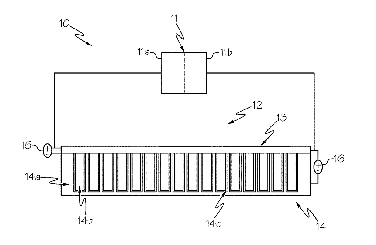
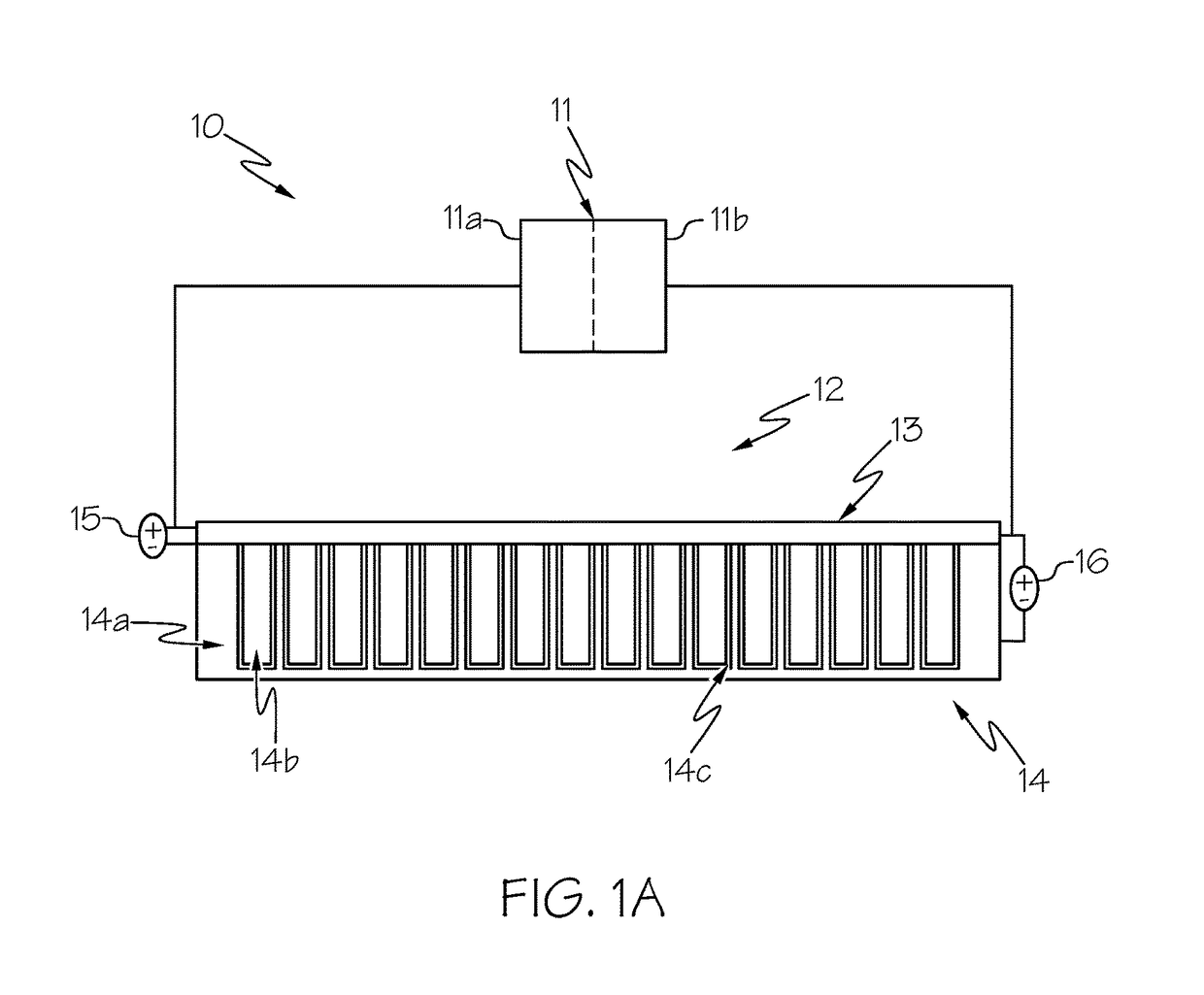
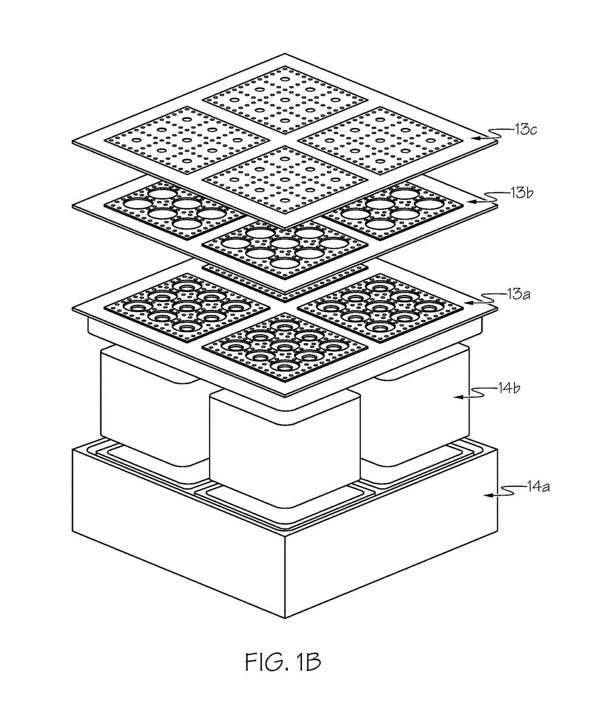
The present invention is a power source that has a chemical power unit and a radioactive power unit integrated with each other. The chemical power unit has a fuel cell and the radioactive power unit has betavoltaic components. The chemical power unit and the radioactive power unit can use the same fuel source. This leads to a more efficient and flexible power source that can provide energy to a sensor system for an extended period of time. The technical effect of the invention is the integration of chemical and radioactive power sources which enables better performance and reliability of the power source system.

Problems solved by technology

State-of-the-art military sensors, such as unattended ground sensors (UGS), constantly consume power to monitor the environment for signal detection although signal of interest often present in less than 0.1% of time.
The majority of the energy (>99%) from the onboard chemical battery is wasted sensing and processing irrelevant data, which limits sensors' useful lifetimes to a few weeks or months even operating from state-of-the-art batteries.
The need to redeploy power-depleted sensors is not only costly and time-consuming but also increases warfighter exposure to danger.
The same problem also exists with commercial wireless sensors for sensing and tracking.
Radioisotope-powered batteries have high energy density and long lifetime, but have low power output, which only suitable for persistent signal detection.

Method used


Image

  • Method of hybrid long operation time power source for wireless sensor nodes
  • Method of hybrid long operation time power source for wireless sensor nodes
  • Method of hybrid long operation time power source for wireless sensor nodes

Examples


Embodiment Construction

[0015]The following detailed description is of the best currently contemplated modes of carrying out the invention. The description is not to be taken in a limiting sense, but is made merely for the purpose of illustrating the general principles of the invention, since the scope of the invention is best defined by the appended claims.

[0016]Various inventive features are described below that can each be used independently of one another or in combination with other features. However, any single inventive feature may not address any of the problems discussed above or may only address one of the problems discussed above. Further, one or more of the problems discussed above may not be fully addressed by any of the features described below.

[0017]Generally, the present invention provides a sensor system with a hybrid battery as a power source. The power source combines high power output of a chemical power source / unit and long lifetime of radioactive power source / unit. The invention can p...


PUM


Abstract

An integrated power source includes a chemical power unit having a fuel cell and a radioactive power unit having betavoltaics. The chemical power unit and the radioactive power unit are integrated with one another to use a common fuel source.

Description

BACKGROUND OF THE INVENTION[0001]The present invention generally relates to sensors and, more particularly, to apparatus and methods of powering sensors.[0002]State-of-the-art military sensors, such as unattended ground sensors (UGS), constantly consume power to monitor the environment for signal detection although signal of interest often present in less than 0.1% of time. The majority of the energy (>99%) from the onboard chemical battery is wasted sensing and processing irrelevant data, which limits sensors' useful lifetimes to a few weeks or months even operating from state-of-the-art batteries. The need to redeploy power-depleted sensors is not only costly and time-consuming but also increases warfighter exposure to danger.[0003]The same problem also exists with commercial wireless sensors for sensing and tracking. Long life time power source will be needed to power wireless sensors to enable the internet of things.[0004]Chemical batteries have low energy density, but can pr...

Claims


Application Information

Patent Timeline
IPC IPC(8): G21H1/06H01M8/1018
CPCG21H1/06H01M8/1018H01M2300/0082H01M2250/30H01M2008/1095H01M16/003Y02E60/50G21H1/02
Inventor TIN, STEVEN
Owner HONEYWELL INT INC
Learn More