Eureka AIR delivers breakthrough ideas for toughest innovation challenges, trusted by R&D personnel around the world.

Electron energy loss spectrometer

a technology of energy-loss spectrum and electron microscopy, which is applied in the field of electron microscopy and spectrometry, can solve the problems of optics being somewhat out of focus, two problems becoming particularly noticeable, and the intensity of energy-loss spectrum falling off rapidly with energy loss

Active Publication Date: 2017-07-20
GATAN INC
View PDF3 Cites 8 Cited by
  • Summary
  • Abstract
  • Description
  • Claims
  • Application Information

AI Technical Summary

Benefits of technology

The invention is about a new electron energy loss spectrometer that can measure the energy of electrons in a more accurate and reliable way at lower operating voltages and higher energy resolutions. The new spectrometer addresses two problems that were previously present at lower operating voltages and higher energy resolutions: the lens effect and the range of electron energies through the spectrometer optics. The invention also addresses the issue of scattered electrons and their impact on the spectrum quality. The new spectrometer has a simplified design and is more effective in trapping the scattered electrons, resulting in better spectrum quality.

Problems solved by technology

The intensity of the energy-loss spectrum falls off rapidly with energy loss, and EELS studies are typically limited to about 3 keV energy loss.
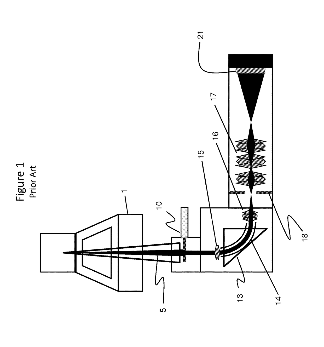
At lower operating voltages and higher energy resolutions, two problems become particularly noticeable, whenever the bending magnet drift tube is employed to shift the spectrum.
Second, because the range of electron energies through the rest of the spectrometer optics has now changed, that optics is somewhat out of focus.
These problems cause the EEL spectrum to defocus slightly, limiting energy resolution and spectrum quality.
In practice, this is very difficult and EEL spectrometers typically suffer from what are called reflections.
The artifacts can obscure spectral features, make their analysis impossible, and / or be wrongfully interpreted as spectral information itself.
While reasonably effective this does not stop all scattered electrons and some artifacts typically remain.

Method used


Image

  • Electron energy loss spectrometer
  • Electron energy loss spectrometer
  • Electron energy loss spectrometer

Examples


Embodiment Construction

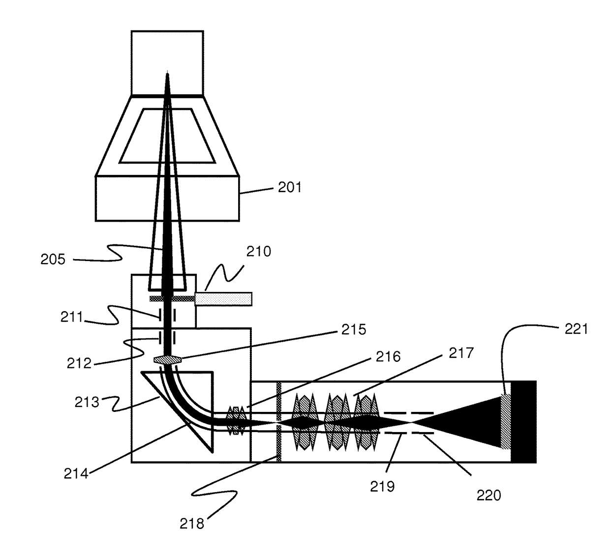
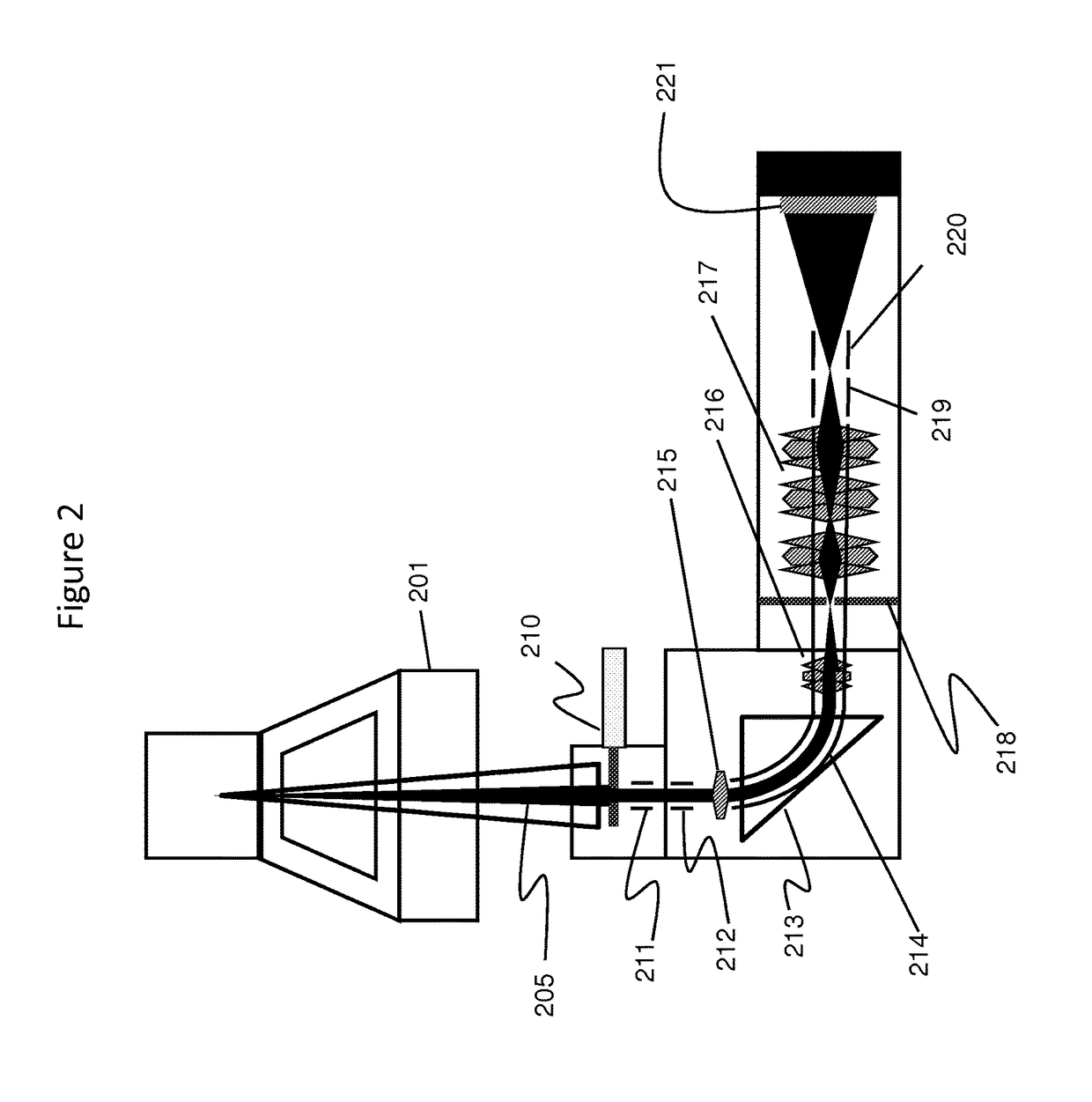
[0011]With reference to FIG. 2, in an embodiment of the invention, there is a beam 205 emerging from a transmission electron microscope 201 entering the spectrometer through an aperture 210. An electrostatic lens system 211, 212 and 219, 220 is respectively added to the prior art device before and after the bending magnet drift tube 214. These lenses are adjusted as a function of the bending magnet drift tube voltage so that the net focal length is constant and no defocusing occurs. Reference items 211 and 220 depict grounded tubes and 212, 219 are voltage biased lens elements.

[0012]In a further embodiment, the isolated drift tube 214 is extended throughout the entire optics 216, 217, not just the bending magnet 214, so that the range of electron energies in all the optics is constant and no defocusing occurs.

[0013]In a further embodiment, the electrostatic lenses 212, 219 are round electrostatic lenses. In a further embodiment the electrostatic lenses are located at the start 212 a...


PUM


Abstract

An electron energy loss spectrometer for electron microscopy is disclosed having an electrically isolated drift tube extending through the bending magnet and through subsequent optics that focus and magnify the spectrum. An electrostatic or magnetic lens is located either before or after or both before and after the drift tube and the lens or lenses are adjusted as a function of the bending magnet drift tube voltage to maintain a constant net focal length and to avoid defocusing. An energy selecting slit is included in certain embodiments to cleanly cut off electrons dispersed outside the energy range incident on the detector, thereby eliminating artifacts caused by unwanted electrons scattering back into the spectrum.

Description

CROSS REFERENCE TO RELATED APPLICATIONS[0001]This PCT application claims the benefit under 35 USC 119(e) of provisional application Ser. No. 62 / 018,294 filed on Jun. 27, 2014 and entitled “Electron Energy Loss Spectrometer” and also of provisional application Ser. No. 62 / 160,381 filed on May 12, 2015 and bearing the same title. The entire disclosures of the earlier-filed provisional applications are incorporated herein by reference.FIELD OF THE INVENTION[0002]The invention relates generally to the field of electron microscopy and spectrometry.BACKGROUND OF THE INVENTION[0003]Electron Energy-Loss Spectroscopy, EELS, is typically practiced on Transmission Electron Microscopes (TEM) at 200-300 kV operating voltage and around 1 cV energy resolution. Recently there has been a drive to much lower operating voltage (e.g. 15 kV) and higher energy resolution (e.g. 5 meV). The electron energy-loss spectrum extends from 0 to many keVs energy-loss. The intensity of the energy-loss spectrum fall...

Claims


Application Information

Patent Timeline
Patent Type & Authority Applications(United States)
IPC IPC(8): H01J37/05H01J37/28H01J37/244H01J37/12H01J37/147
CPCH01J37/05H01J37/12H01J37/147H01J37/244H01J2237/2802H01J2237/12H01J2237/053H01J2237/24485H01J37/28H01J2237/057H01J2237/055
Inventor GUBBENS, ALEXANDER JOZEFTREVOR, COLINTWESTEN, RAY DUDLEYBARFELS, MELANIE
Owner GATAN INC
Why Eureka
Eureka Blog
Learn More