
Deposition apparatus

Active Publication Date: 2017-07-27
CANON ANELVA CORP
View PDF4 Cites 0 Cited by
  • Summary
  • Abstract
  • Description
  • Claims
  • Application Information

AI Technical Summary

Benefits of technology

The patent text describes three technical aspects to improve the process of forming films on substrates in a deposition apparatus. The first aspect aims to prevent the substrate from deforming during transportation. The second aspect aims to increase the throughput, or the speed at which multiple substrates can be processed simultaneously. The third aspect aims to resolve issues that arise when multiple substrates are processed simultaneously. Overall, these technical aspects aim to enhance the efficiency and effectiveness of the deposition apparatus.

Problems solved by technology

Particularly in a resin substrate or the like, the deformation amount can be large and pose a problem.
In this deposition apparatus, the throughput is low because of an increase in the transportation count and the transportation time.
Additionally, in a case in which a simultaneous process of a plurality of substrates is enabled to improve the throughput, a problem that one deposition unit forms a film on another deposition unit arises.

Method used


Image

  • Deposition apparatus
  • Deposition apparatus
  • Deposition apparatus

Examples


Embodiment Construction

[0040]The present invention will now be described with reference to the accompanying drawings using an exemplary embodiment.

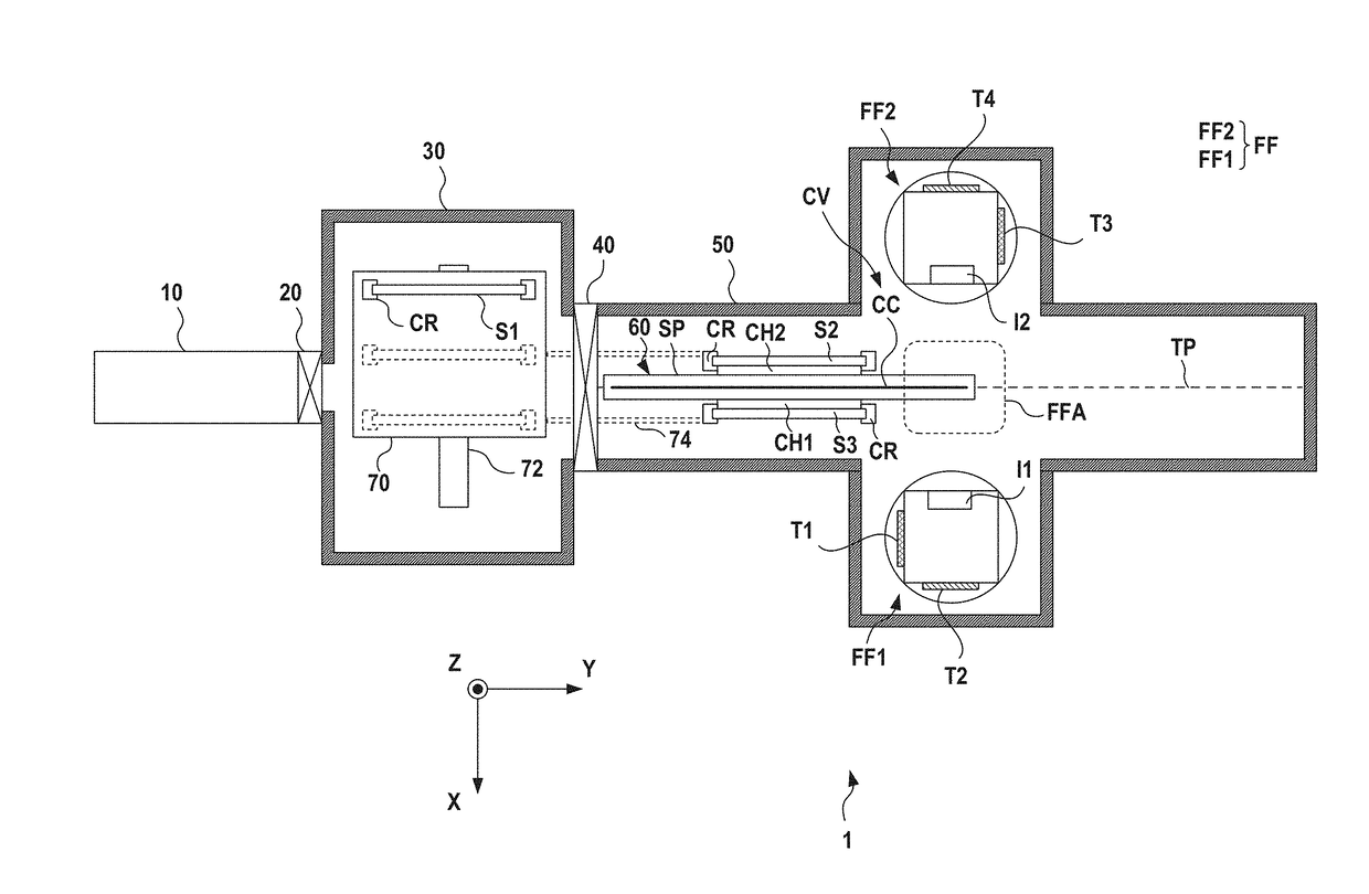
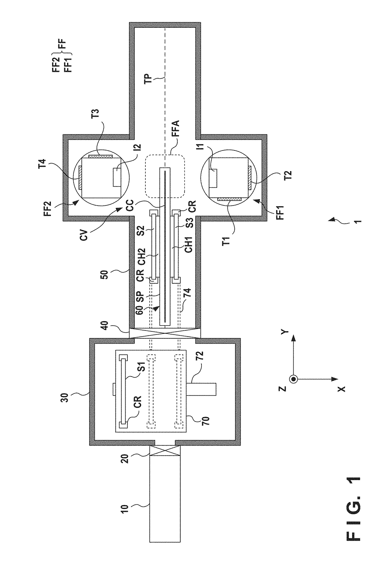
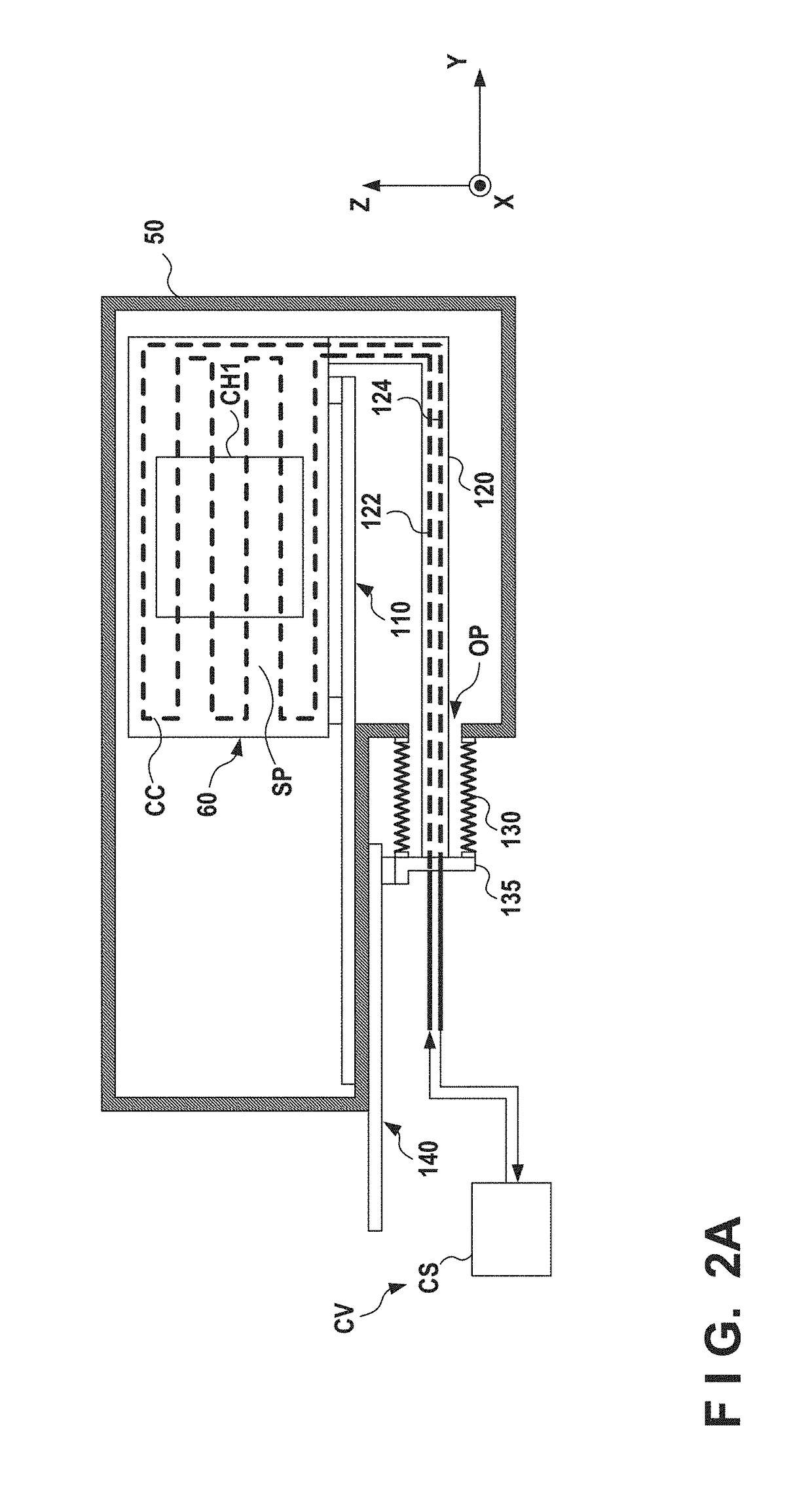
[0041]FIG. 1 is a schematic sectional view showing a deposition apparatus 1 according to one embodiment of the present invention taken along a plane parallel to a horizontal plane. FIGS. 2A and 2B are sectional views showing part of the deposition apparatus 1 taken along a plane along the vertical direction. Here, the XY plane is a plane parallel to the horizontal plane, and the Z-axis is an axis parallel to the vertical direction. The deposition apparatus 1 is configured as an apparatus that forms a film on a substrate S (S1, S2, . . . .) In this specification, symbols like S1, S2, S3, and S4 are used to discriminate a plurality of substrates from each other. If the substrates need not be discriminated from each other, they are described as the substrates S. Each substrate S can be transported and processed in a state in which it is held by, for example, a car...


PUM

PropertyMeasurementUnit
Areaaaaaaaaaaa

Abstract

A deposition apparatus includes a chamber, a holding unit configured to hold a substrate in the chamber, a driving unit configured to move the holding unit holding the substrate such that the substrate passes through a deposition area in the chamber, a deposition unit configured to form a film on the substrate passing through the deposition area by supplying a deposition material to the deposition area, and a cooling unit configured to cool the holding unit.

Description

[0001]This application is a continuation of International Patent Application No. PCT / JP2015 / 067908 filed on Jun. 22, 2015, and claims priority to Japanese Patent Application No. 2014-209380 filed on Oct. 10, 2014, the entire content of both of which is incorporated herein by reference.BACKGROUND OF THE INVENTION[0002]Field of the Invention[0003]The present invention relates to a deposition apparatus for forming a film on a substrate.[0004]Description of the Related Art[0005]In the manufacture of an electronic device, various films can be formed on a substrate by a plasma process such as plasma PVD or plasma CVD. For example, PTL 1 describes a deposition apparatus that forms a film on a substrate while transporting the substrate. In such a deposition apparatus, a substrate under a process may be heated beyond an appropriate temperature for the process or deformed. Particularly in a resin substrate or the like, the deformation amount can be large and pose a problem.[0006]On the other ...

Claims


Application Information

Patent Timeline
IPC IPC(8): C23C14/50C23C14/54H01J37/34C23C14/34
CPCC23C14/50C23C14/3464H01J37/3488H01J37/3411C23C14/541C23C14/022C23C14/04C23C14/566C23C14/568H01L21/67109H01L21/67201H01L21/67213H01L21/67712H01L21/6776C23C14/34C23C16/4586
Inventor NOZAWA, NAOYUKIMATSUKI, NOBUOSAKAMOTO, REIJIISHIHARA, MASAHITO
Owner CANON ANELVA CORP
Learn More