
Flexible Wind Turbine Apparatus

a wind turbine and flexible technology, applied in the field of wind turbines, can solve the problems of noise, aesthetic pollution, cost, and competition with conventional energy sources, and achieve the effects of improving the cost competitiveness of wind energy, generating a good deal of electricity, and little or no disturbance to surrounding land or buildings

Inactive Publication Date: 2017-07-27
OLIVERA REINALDO IVAN
View PDF2 Cites 4 Cited by
  • Summary
  • Abstract
  • Description
  • Claims
  • Application Information

AI Technical Summary

Benefits of technology

This patent describes a wind turbine that can be easily scaled up or down, with one airfoil being the minimum size. This design allows for the capture of wind energy in urban settings without causing disturbance to buildings or land. The turbine can be made in a toy size model or a utility size model, and can be customized with different airfoil shapes and arrangements to match the shape of a building or land. The scalability of the design makes it ideal for both toy and marketing tools, and helps improve the cost competitiveness of wind energy.

Problems solved by technology

While this expanded use of wind energy, known for being a clean and renewable, has obvious benefits over traditional fossil fuels, the capture of wind does not come without challenges.
One of the biggest obstacles to a wide acceptance of the use of wind energy as a power source is the competition with conventional energy sources in terms of cost.
Another monetary obstacle faced by wind energy expansion is that sites good for wind energy production are located remotely from sites that need the electricity.
This use of remote locations for wind farms not only stems from the fact that there may be more wind to capture in rural expanses but is also due to the intrusiveness of traditional wind turbines which may cause noise and aesthetic pollution.
This noise, combined with the space requirements and what some may feel are aesthetically displeasing features make wind turbines impractical to use near or within cities or towns.

Method used


Image

  • Flexible Wind Turbine Apparatus
  • Flexible Wind Turbine Apparatus
  • Flexible Wind Turbine Apparatus

Examples


Embodiment Construction

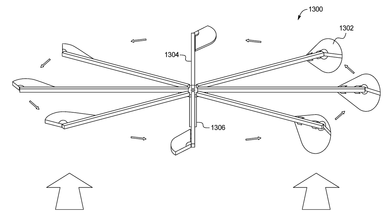
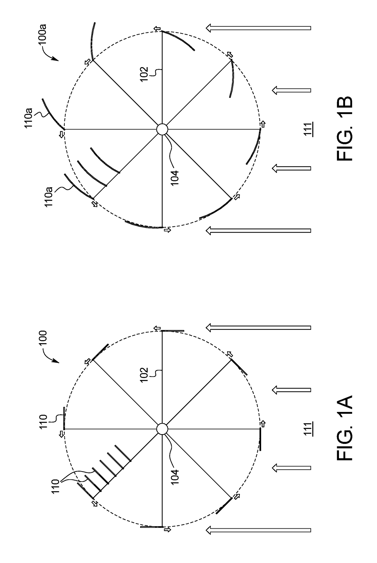
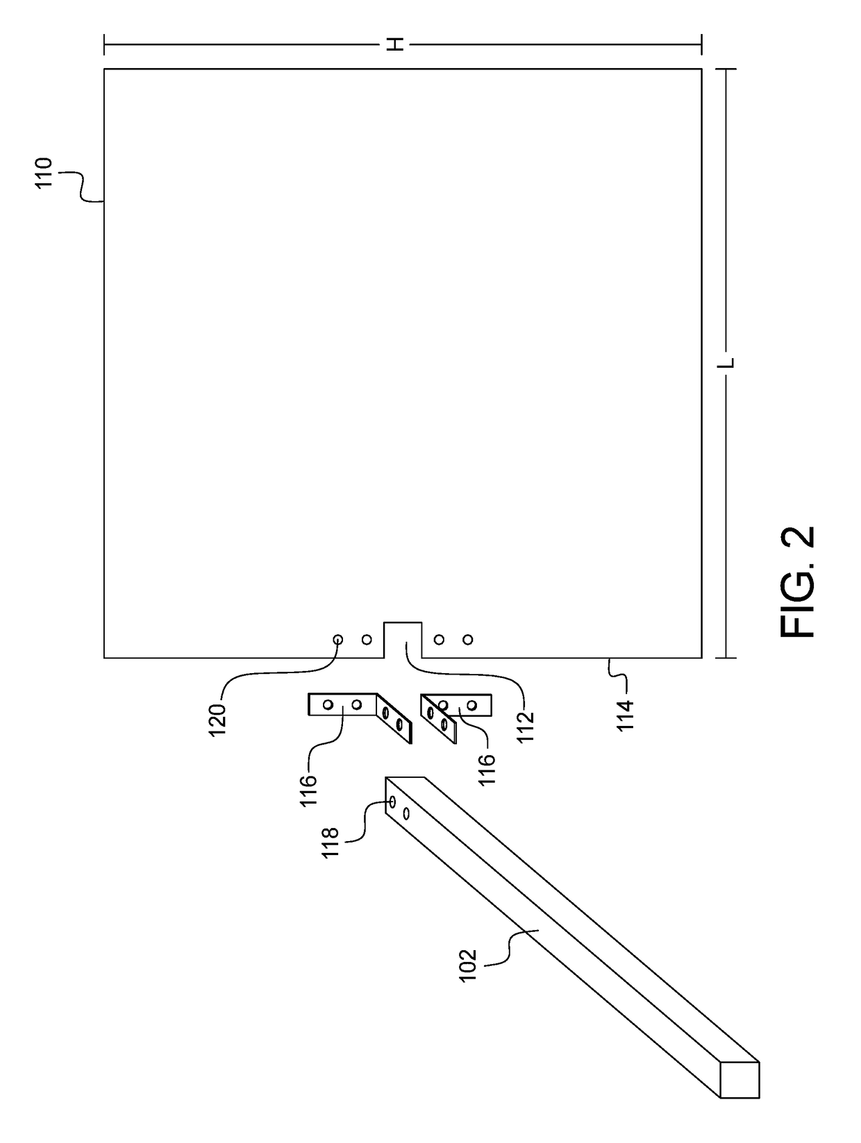
[0039]As shown in FIG. 1A, the wind turbine 100 includes one or more support arms 102 that extend from a vertical central rotating shaft 104. A first shaft end 106 is secured to a support base 108 as seen in FIG. 3, and the one or more support arms 102 are connected to the shaft 104 as a second shaft end 110. Each airfoil includes a height H parallel to the shaft and a length L transverse to the height H as shown in FIG. 2. While each of the illustrated embodiments is a vertical axis wind turbine, the airfoil designs described herein may be modified for use on a horizontal axis wind turbine as well.

[0040]Referring to FIG. 1A, a wind turbine 100 includes a plurality of support arms 102 extending perpendicular to a central rotating shaft 104 in a circular pattern. Each support arm 102 may include a single or multiple square airfoils 110 mounted to and extending to a single side of the support arm 102. Although the embodiments illustrated in FIGS. 1A-5B include square-shaped airfoils, ...


PUM


Abstract

An airfoil for a wind turbine apparatus includes an airfoil body having an arcuate shape extending between a first end and a second end and an airfoil support secured to a midpoint on the airfoil body and connected to the outer end of the support arm. The airfoil body includes a first portion adjacent to the first end and a second portion adjacent to the second end. The first end and the second end are secured to the support arm, and the body of the airfoil is comprised of material capable of flexing in response to wind pressure. The first and second portions of the airfoil body extend away from each other in an extended position and collapse together in a collapsed position, and the orientation of the airfoil relative to the direction of the wind causes the airfoil to move between the open and closed positions.

Description

CROSS-REFERENCE TO RELATED APPLICATIONS[0001]This application incorporates by reference and claims the benefit of priority to U.S. Provisional Patent Application No. 62 / 281,855 filed Jan. 22, 2016.BACKGROUND OF THE INVENTION[0002]The present subject matter relates generally to a wind turbine. More specifically, the present invention relates to a flexible, scalable wind turbine apparatus.[0003]Wind is an important source of renewable energy. According to the US Department of Energy, the amount of wind energy captured in the United States has tripled since the year 2000. Based off projections from the US Department of Energy, this trend of expanded wind energy capture will continue, reaching six times the current levels in the US by 2050. While this expanded use of wind energy, known for being a clean and renewable, has obvious benefits over traditional fossil fuels, the capture of wind does not come without challenges.[0004]One of the biggest obstacles to a wide acceptance of the use...

Claims


Application Information

Patent Timeline
Patent Type & Authority Applications(United States)
IPC IPC(8): F03D3/06F03D3/02F03D3/00
CPCF03D3/068F03D3/005F03D3/02F05B2240/211F05B2250/11F05B2250/232F05B2250/12F05B2250/121F05B2250/70Y02B10/30Y02E10/74F05B2240/311
Inventor OLIVERA, REINALDO IVAN
Owner OLIVERA REINALDO IVAN
Learn More