Unit cell for redox flow battery, for reducing pressure drop caused by electrolyte flow in stack

a technology of redox flow and unit cell, which is applied in the direction of electrochemical generators, fuel cells, electrical equipment, etc., can solve the problems of increasing the difficulty of assembly, increasing the volume and weight of the stack, increasing the cost of the bipolar plate, etc., and achieves the effect of reducing the system cost, reducing the pressure drop in the stack, and reducing the power consumption of the pump

Active Publication Date: 2019-05-30
H2 METAL
View PDF1 Cites 1 Cited by
  • Summary
  • Abstract
  • Description
  • Claims
  • Application Information

AI Technical Summary

Benefits of technology

[0038]According to the present invention, it is possible to lower the pressure drop in the stack and use a pump with low power consumption at the same flow rate, and as a result, it is possible to reduce the system cost and reduce the power consumption by the pump, thereby increasing the system efficiency.
[0039]Particularly, in the present invention, a channel is formed in a flow frame without forming a channel in a bipolar plate to reduce the use of expensive materials, thereby enhancing cost competitiveness. Further, the electrolyte passes between two or more rectangular felt electrodes to reduce the pressure drop of the electrolyte, thereby improving the system efficiency.

Problems solved by technology

Particularly, in the case of using a technique of forming a channel on a bipolar plate in the related art, there is a problem that the cost of the bipolar plate increases and the volume and weight of the stack increase.
In addition, in the case of forming a flow path by processing an electrode felt, there is a problem in that the difficulty of the assembly increases.

Method used


Image

  • Unit cell for redox flow battery, for reducing pressure drop caused by electrolyte flow in stack
  • Unit cell for redox flow battery, for reducing pressure drop caused by electrolyte flow in stack
  • Unit cell for redox flow battery, for reducing pressure drop caused by electrolyte flow in stack

Examples


Embodiment Construction

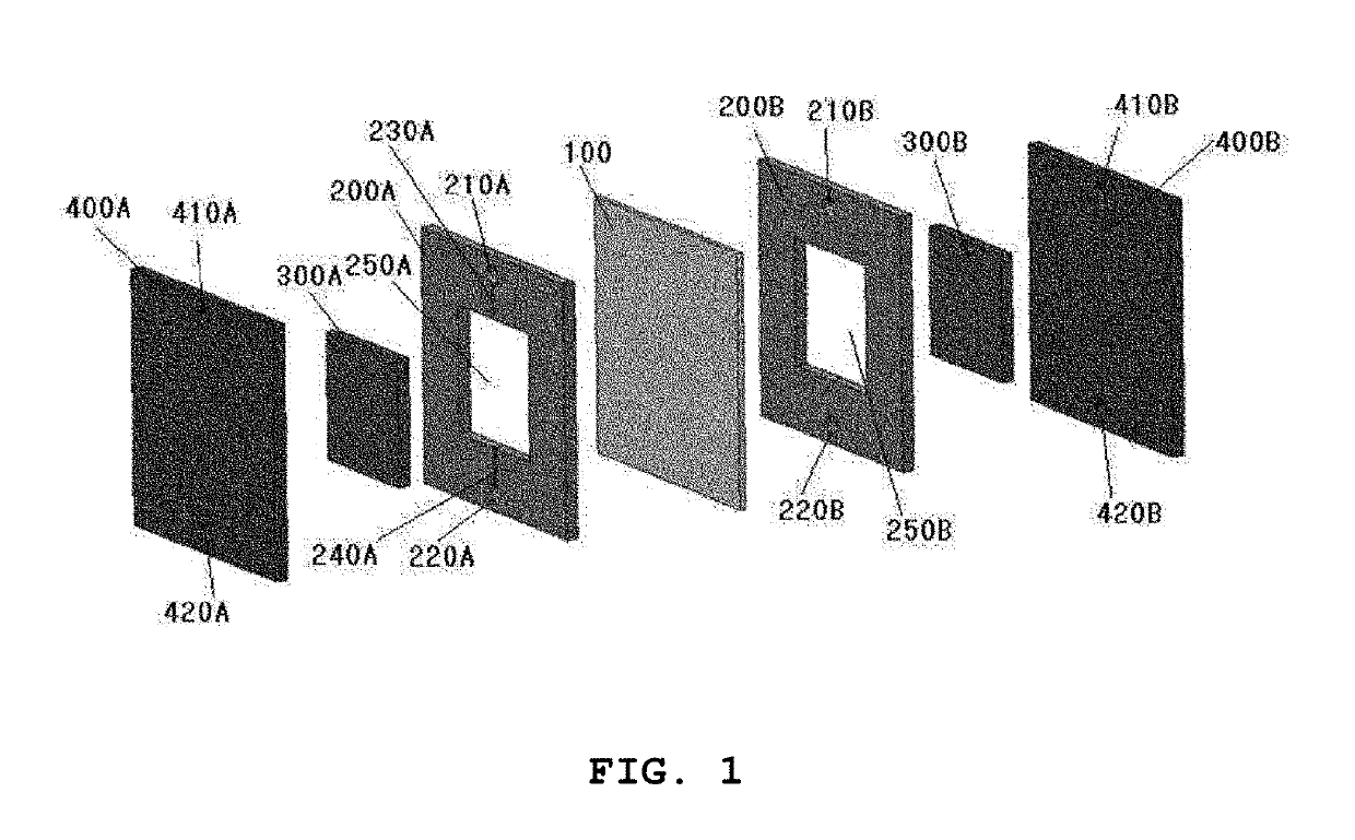
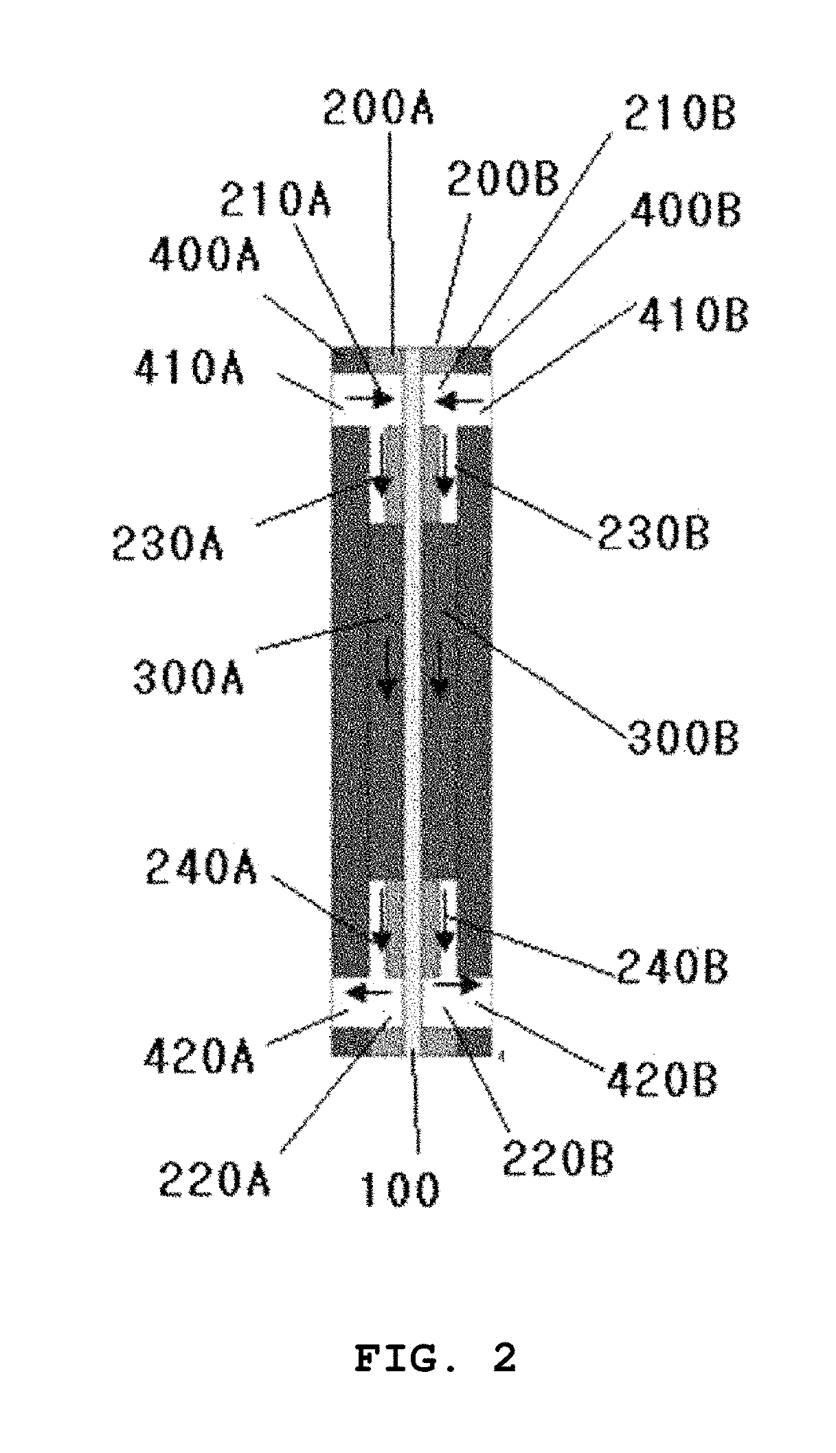
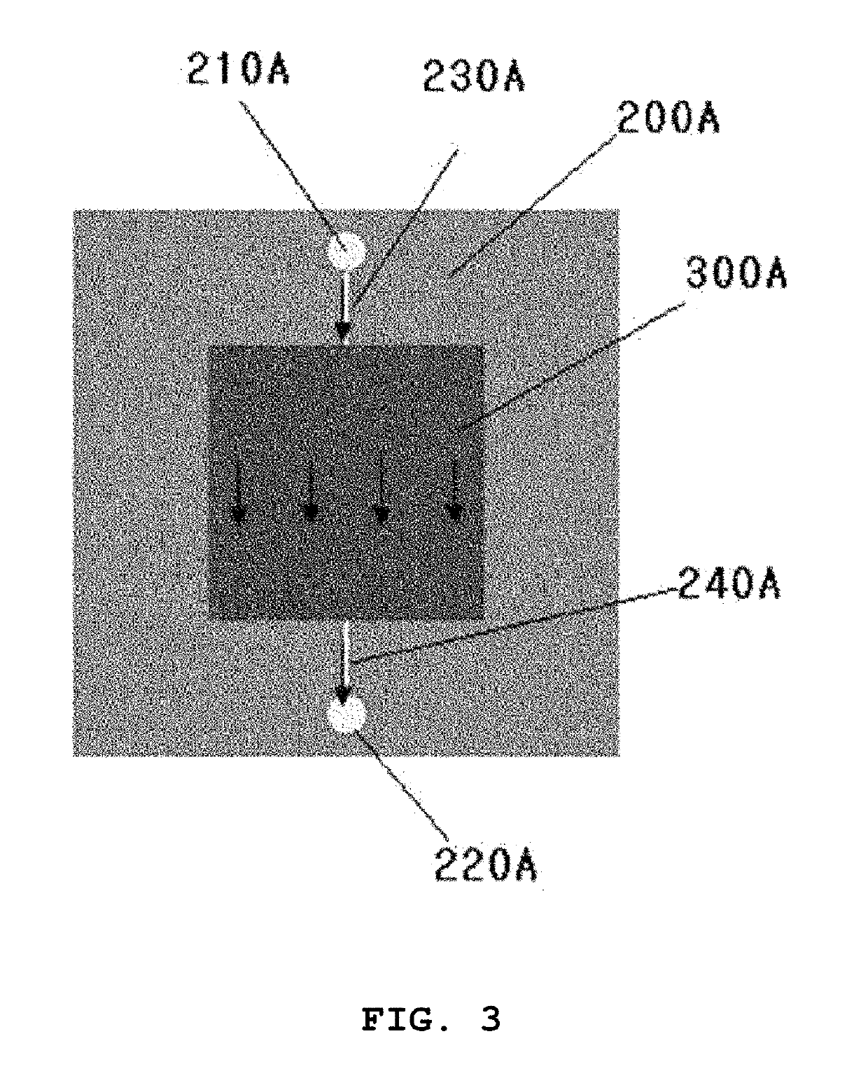
[0055]FIG. 6 is an exploded perspective view of a unit cell of a stack for a redox flow battery of the present invention. It is shown that flow frames 200A and 200B and bipolar plates 4000A and 4000B are disposed at both sides of an ion-exchange membrane 1000 and two or more electrodes 3100A, 3200A, 3300A, and 3400A are disposed in two or more cavities 2610A, 2620A, 2630A, and 2640A (see FIG. 7) formed inside an outer frame 2700A of the flow frame 2000A, respectively. Also, similarly, it is shown that two or more electrodes 3100B, 3200B, 3300B, and 3400B are disposed in two or more cavities formed inside the flow frame 2000B.

[0056]The widths of the electrodes 3100A, 3200A, 3300A, and 3400A; 3100B, 3200B, 3300B, and 3400B shown in FIG. 6 are shown to be constant, but are not limited thereto, and the widths can be changed.

[0057]For reference, in the present invention, the outer frame 2700A is used to mean a frame excluding the side support walls 2311A, 2321A, 2331A; 2411A, 2421A, and ...


PUM

PropertyMeasurementUnit
depthsaaaaaaaaaa
depthaaaaaaaaaa
rectangular shapeaaaaaaaaaa

Abstract

Provided is a redox flow battery stack comprising: an ion-exchange membrane (1000); two flow frames (2000A, 2000B) disposed on both sides of the ion-exchange membrane (1000), respectively; two bipolar plates (4000A, 4000B) disposed outside the flow frames (2000A, 2000B), respectively; and electrodes disposed in cavities inside outer frames of the flow frames (2000A, 2000B), respectively, in which at least two electrodes are disposed in the flow frames, respectively, and at least three furrows in which the electrolyte flows are formed between electrodes or between the electrode and the outer frame in the flow frame.

Description

BACKGROUND OF THE INVENTIONField of the Invention[0001]The present invention relates to a unit cell for a redox flow battery, and more particularly, to a unit cell for a redox flow battery for reducing pressure drop in a flow frame.Description of the Related Art[0002]A redox flow battery is one of core products closely related to renewable energy, reduction in greenhouse gas, rechargeable batteries, and smart grids, which have been attracting the greatest attention in the world in recent years. A fuel cell is a product which is expanding rapidly in the market in the world as a renewable energy source to replace fossil fuels without emission of pollutants. Currently, most of the energy is derived from fossil fuels, but there is a problem in that the use of such fossil fuels has serious adverse environmental impacts such as air pollution, acid rain and global warming, and low energy efficiency.[0003]In recent years, in order to solve the problems caused by the use of such fossil fuels...

Claims


Application Information

Patent Timeline
Patent Type & Authority Applications(United States)
IPC IPC(8): H01M8/0258H01M8/0273H01M8/18
CPCH01M8/0258H01M8/0273H01M8/188Y02E60/50H01M8/18
Inventor HAN, SHINHAN, CHANG HOONHUH, JEE HYANGKIM, YUJONG
Owner H2 METAL
Why Eureka
Try Eureka