
Device for rapid diagnostic tests to detect antigens with improved sensitivity

a technology of antigen detection and rapid diagnostic testing, which is applied in the field of rapid diagnostic testing of blood samples, can solve the problems of false negative test, affecting the detection performance or sensitivity of the rdt assay kit, and the increase of the number of steps required for the assay,

Active Publication Date: 2017-07-27
TOKITAE LLC +1
View PDF17 Cites 22 Cited by
  • Summary
  • Abstract
  • Description
  • Claims
  • Application Information

AI Technical Summary

Benefits of technology

The patent describes a rapid diagnostic testing device for biological samples, such as blood samples. The device includes a channeled construct for separating unwanted components from the sample and forming a purified sample. A lateral flow unit is connected to the channel construct and cassette housing for detecting one or more particular analytes. The device can be used to diagnostically test for the presence of various antigens or antibodies in a blood sample. The technical effects of the device include increased efficiency in sample processing and detection of specific analytes.

Problems solved by technology

This in turn affects the detection performance or sensitivity of the RDT assay kit.
The small volume of sample affects detection, particularly if the level of analyte in the sample is low and can lead to false negative test results.
Disadvantages of the methods disclosed in the art include a greater number of steps required for the assay and / or the increased cost of reagents / materials required for the assays.

Method used


Image

  • Device for rapid diagnostic tests to detect antigens with improved sensitivity
  • Device for rapid diagnostic tests to detect antigens with improved sensitivity
  • Device for rapid diagnostic tests to detect antigens with improved sensitivity

Examples


example 1

Effect of a Conjugate Zone (Conjugate Pad) Location

[0089]RDT device constructs: The different RDT device constructs were made for testing the detection assay performance which are shown in FIG. 8A. In a benchmark device, the conjugate zone and detection zone were separated by a sample receiving zone, which was used herein as a control and is referred to herein as “Benchmark 1” (or B1 as shown in FIG. 8A). The conjugate zone of a Benchmark 1 was moved up to be adjacent to detection zone forming device construct I, or moved down such that it was further away from detection zone forming device construct II, or an additional conjugate pad (2×) was added to its original location and formed device construct III. A channeled construct was placed on top of the conjugate / sample receiving zone, and the housing was closed until testing. Different zones, such as buffer reservoir, sample receiving zone, conjugate zone, detection zone and wicking pad on the lateral flow unit are represented by B,...

example 2

Effect of Particle Type in Benchmark 1 Configuration

[0092]HRP2 was tested using other available benchmark products (Benchmark 1 or B1, Benchmark 2 or B2) and a product developed in the laboratory (“device construct V”) using cellulose nanobeads as the conjugate particles. The devices construct V and Benchmark 2 were different than the Benchmark 1 in their configurations. The conjugate zones of the Benchmark 2 device and device construct IV were adjacent to the detection zones, which did not allow complete mixing of analytes and conjugate particles before the conjugate particles reached the test lines. This led to less performance improvement even if a channeled construct was added. Different device constructs, such as Hybrid 1 (H1), Hybrid 2 (H2), and Hybrid 3 (H3) were made by using a conjugate pad, a detection pad or a sample receiving pad from different device constructs, such as, Benchmark 1, Benchmark 2 and device construct IV. Hybrid 1 was made by replacing the conjugate pad o...

example 3

Detection of Analyte HRP2 and Quantification of Sensitivity at Low HRP2 Concentration

[0095]In configuration of Benchmark 1, the performances of channeled constructs were tested in broader concentration range to estimate the improvement on limit of detections, for both cellulose nanobeads (CNB) of device construct IV and conjugate particles of Benchmark 1. The quantified results were shown in FIG. 11. For either particle type, there are nearly 10× improvements in both signal intensities and estimated lower detection limits (FIG. 11).

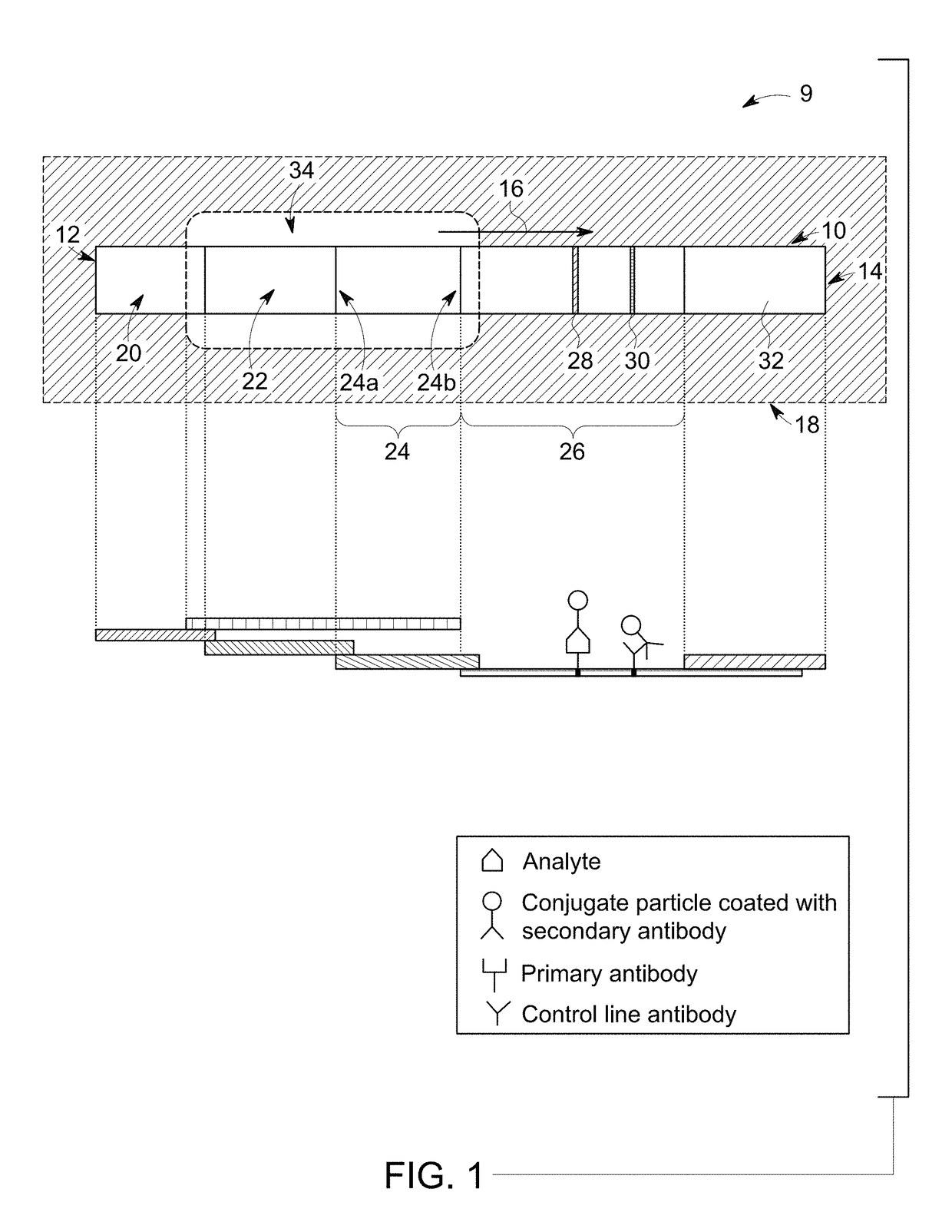
[0096]A configuration of the RDT device (as shown in FIG. 1) having a sample receiving zone between conjugate zone and detection zone ensured thorough mixing of particles and analytes before the particles pass the test line. In another example, the conjugate zone and the sample receiving zone were also disposed on a single pad, when the conjugate particles were sprayed at one end of the pad, leaving enough distance between conjugate zone and detection zon...


PUM


Abstract

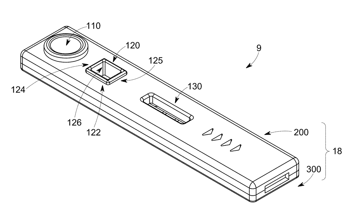
A rapid diagnostic testing device for testing of a biological sample is provided. The device comprises a channeled construct, at least one lateral flow unit, and a cassette housing. The channeled construct is configured to receive a biological sample to form at least partially purified biological sample. The lateral flow unit is at least partially disposed in the cassette housing. The lateral flow unit comprises: a sample receiving zone, a conjugate zone and a detection zone. The sample receiving zone is operatively coupled to the channeled construct for receiving the partially purified biological sample comprising at least one analyte. The conjugate zone comprising a conjugate particle to bind the analyte is disposed adjacent to the first side of the sample receiving zone. The detection zone is disposed adjacent to the second side of the sample receiving zone and comprises at least one binding agent for detecting the analyte.

Description

CROSS REFERENCE TO RELATED APPLICATIONS[0001]This application is a continuation in part claims the benefit of U.S. application Ser. No. 15 / 005054, titled “Integration of sample separation with diagnostic tests for improved sensitivity”, filed on Jan. 25, 2016, now copending, which is incorporated herein by reference.FIELD[0002]This application relates generally to an improvement in currently available rapid diagnostic tests (RDTs), particularly RDTs for malaria. In a particular aspect, the application relates to a device for rapid diagnostic testing of a blood sample.BACKGROUND[0003]A rapid diagnostic test (RDT) is a medical diagnostic test that is less time consuming and less labor intensive. RDTs are suitable for preliminary and / or emergency medical screening, for example, for use in medical facilities with limited resources, and offer a useful alternative to microscopy in situations where reliable microscopic diagnosis facility is not available or is not immediately available. RD...

Claims


Application Information

Patent Timeline
IPC IPC(8): G01N33/558G01N33/543
CPCG01N33/54386G01N33/558G01N33/54388
Inventor LI, BINGMISNER, MATTHEW JEREMIAHMOORE, DAVID ROGERNICHOLS, KEVIN PAUL FLOODCATE, DAVIDROSEN, MATTHEW F.
Owner TOKITAE LLC
Learn More