Object detection system and method

a technology of object detection and object detection, applied in the field of object detection systems, can solve the problems of significantly lower accuracy of outdoor lighting control, lower energy consumption, and over-specified solutions, and achieve the effects of reducing illumination intensity, high reflectivity, and high signal quality

Active Publication Date: 2017-07-27
SIGNIFY HLDG BV
View PDF9 Cites 11 Cited by
  • Summary
  • Abstract
  • Description
  • Claims
  • Application Information

AI Technical Summary

Benefits of technology

[0013]The invention is based on the recognition that the illumination intensity for a time of flight system can be adapted according to a measured signal quality, for example in combination with a required signal quality. For example, parts of the background of the scene with high reflectivity give higher signal quality and therefore may require lower illumination intensity.
[0014]In this way, an optimized illumination intensity for time of flight sensing can be obtained. The intensity may for examp

Problems solved by technology

However, some applications such as outdoor lighting control in fact require significantly lower accuracy depending on the sensing task and object pro

Method used


Image

  • Object detection system and method
  • Object detection system and method
  • Object detection system and method

Examples


Embodiment Construction

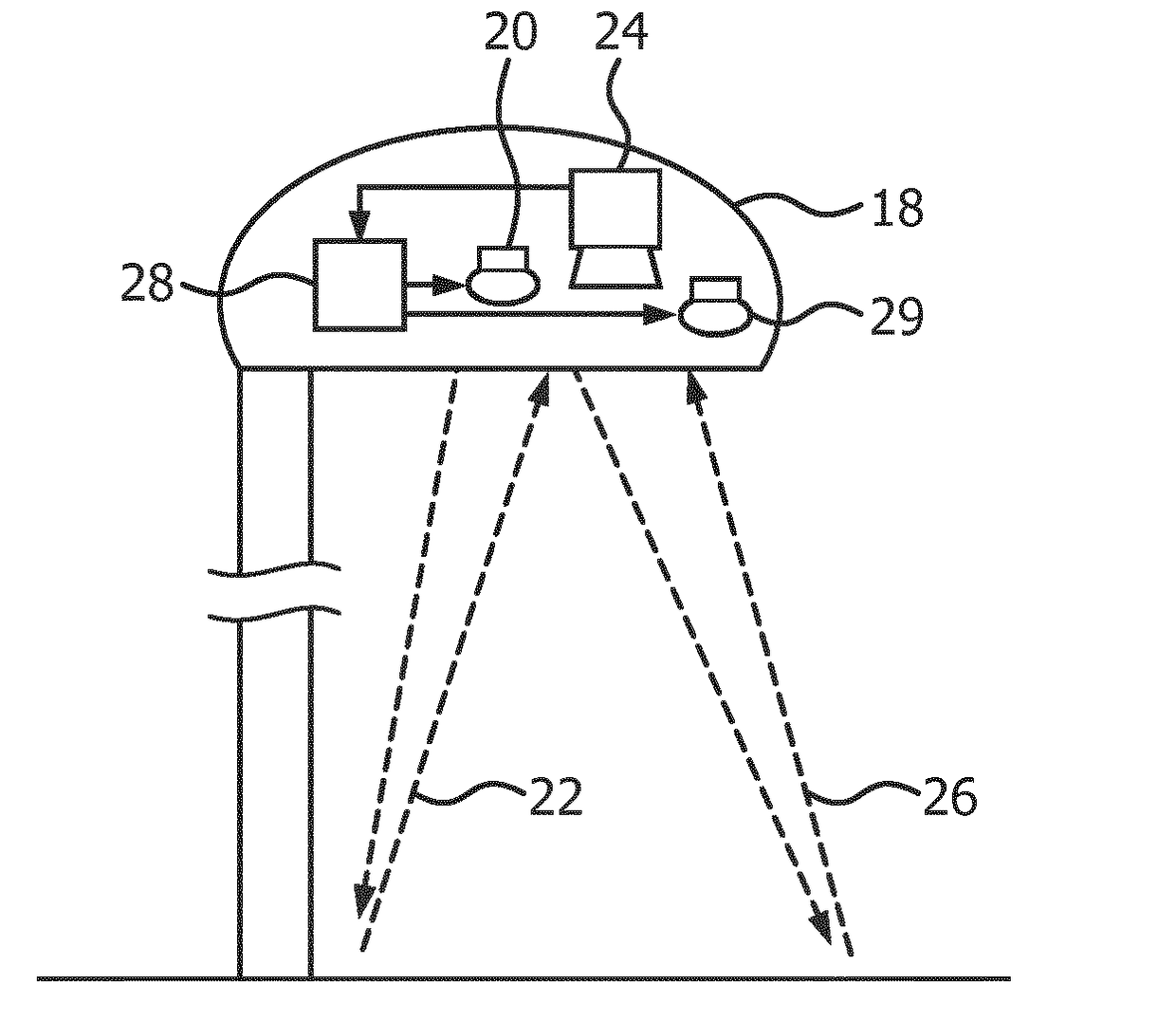
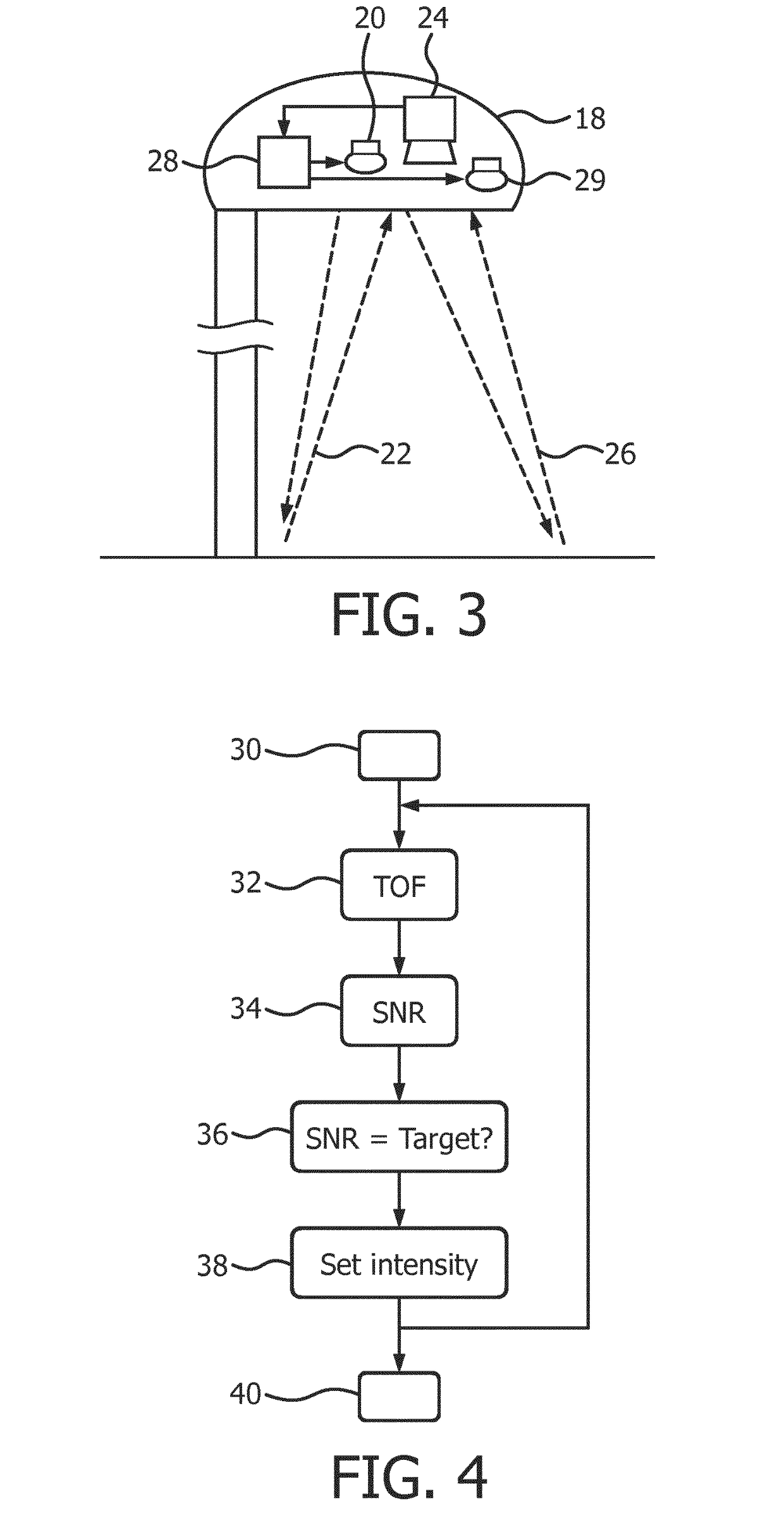
[0036]The invention provides an object detection system for object detection within a field of view. A light source provides detection illumination to the field of view and a sensor senses reflected light from the field of view. Time of flight analysis is used to provide distance or presence information for objects within the field of view. The controller is adapted to derive a signal quality parameter relating to the distance or presence information and to control the light source intensity in dependence on the signal quality parameter. In this way, energy savings are made possible by adapting the detection system settings to the scene being observed.

[0037]By controlling the light source intensity, the transmitted optical power is adapted based on the detection task, so that lower power consumption is achieved and less thermal energy is generated. Lower power consumption may for example enable devices powered by solar energy or batteries to operate for longer periods. Reduced therm...


PUM


Abstract

An object detection system is for object detection within a field of view. A light source provides detection illumination to the field of view and a sensor senses reflected light from the field of view. Time of flight analysis is used to provide distance or presence information for objects within the field of view. The controller is adapted to derive a signal quality parameter relating to the distance or presence information and to control the light source intensity in dependence on the signal quality parameter. In this way, energy savings are made possible by adapting the detection system settings to the scene being observed.

Description

FIELD OF THE INVENTION[0001]The invention relates to object detection systems, for example for use in controlling a lighting system to provide energy savings by monitoring activity.BACKGROUND OF THE INVENTION[0002]Object detection can be used by a lighting system to provide automated control of the lighting, for example to provide energy savings when the lighting is not needed.[0003]Object detection can be based on mapping the range to objects within a field of view using time of flight sensor principles. Time of flight measurement is based on active illumination that is projected onto the observed scene. The reflected light from the active illumination source is captured by a sensor which measures the phase between the transmitted and received illumination, from which the time of flight and therefore range can be derived. By analyzing the range information for the full field of view, objects can be identified using image analysis techniques.[0004]The accuracy of the phase measureme...

Claims


Application Information

Patent Timeline
IPC IPC(8): G01S7/491G01S17/32H05B37/02G01S17/02G01S7/4911H05B44/00G01S17/04G01S17/894
CPCG01S7/4911G01S17/026G01S7/4918F21W2131/103H05B37/0227F21S8/086G01S17/32G01S17/89G01S17/04H05B47/105Y02B20/40G01S17/894H05B47/115H05B47/125
Inventor BROERS, HARRYRAJAGOPALAN, RUBEN
Owner SIGNIFY HLDG BV
Why Eureka
Try Eureka