Locker system

a locking system and door-to-door technology, applied in the field of locking systems, can solve the problems of unsustainable door-to-door delivery services, unsuitable for domestic cooling devices, and insufficient utilization of their full capacity, so as to facilitate rapid switchover, reduce costs, and facilitate the effect of rapid switchover

Active Publication Date: 2017-08-03
ILLINOIS TOOL WORKS INC
View PDF12 Cites 45 Cited by
  • Summary
  • Abstract
  • Description
  • Claims
  • Application Information

AI Technical Summary

Benefits of technology

[0029]Optionally, the common distribution system comprises a first distribution system for distributing a first heat transfer fluid to exchange heat with a second distribution system; said second distribution system distributes a second heat transfer fluid to exchange heat with each of the one or more compartments. Independent control of the first and second heat transfer fluid permits the temperature within each compartment to be controlled more precisely. This facilitates rapid switchover between the different storage temperatures.
[0030]Optionally, the first heat transfer fluid is a refrigerant and the second heat transfer fluid is a liquid, preferably, the liquid experiences no phase transition over the entire working range of temperature. Optionally, the second heat transfer fluid comprises glycol. Optionally, the second heat transfer fluid can be any one of ethylene glycol, silicone oil, water etc., and compatible mixtures of such fluids, e.g. a mixture of water and glycol at a lower cost.
[0031]Optionally, the temperature controlled storage apparatus comprises a heating system for supplying heat to each of the one or more compartments and therefore, provides more flexibility in the control of the temperature of the compartment, e.g. during very cold spells where chilled or ambient temperatures are required or even defrosting of the compartments. Optionally, the heating system comprises an electric heating element. Optionally electric heating elements are installed to conduct heat to the at least one wall of the lockable storage space or at least one compartment such that the temperature thereof is raised by the operation of electric heating elements. Optionally, the heating system comprises a separate heat transfer fluid in cooperation with the refrigeration system. For increased energy efficiency and to recuperate the heat energy dissipated from the refrigeration system, e.g. condenser, the heating system can utilise the dissipated heat energy to provide heat to a separate heat transfer fluid so as to exchange heat with the compartments.
[0032]Optionally, each of the one or more compartments comprises a heat exchanger and a fan for circulating air from the heat exchanger into the at least one of each of the one or more compartments. The utilization of air circulation improves the heat transfer from the heat transfer fluid to the air within the at least one of each of the one or more compartments and thus the switchover between different storage temperatures can be carried out much promptly. Indeed the improved efficiency means a smaller surface area for heat transfer is required, thus the heat exchanger design can be made simpler. Optionally, the temperature of the at least one of each of the one or more compartments is controlled by controlling the speed of the fan. The utilization of air circulation improves the heat transfer from the heat transfer fluid to the air within at least one compartment and thus the switchover between different storage temperatures can be carried out much more rapidly. By controlling the speed of the fan enables the temperature in each of the compartments to be more reactive to any fluctuation in temperature. For example, using PID based (Proportional, Integral, Derivative) controllers, the temperature in the lockable storage space or compartment can be more accurately tuned to the desired set point level.

Problems solved by technology

However due to fierce competition, supermarkets and the general grocery trade often operates with a comparatively small profit margin, and the additional cost associated with greater coverage in rural areas has made door-to-door delivery services unsustainable.
However the necessity of using refrigerated vehicles to preserve these perishable goods also adds substantially to the cost of delivery.
In consequence, they are not utilising their full capacity and deliveries are limited to close vicinity to the depot.
However the floor space at these convenient locations is often limited and comes with a premium mark up.
Moreover these ACPs do not have provision for storing chilled and frozen goods and their applications are currently limited to electronics, multimedia discs, books and other non-perishable goods that do not require any degree of specialized storage facilities.
In addition it is inconvenient for the customer to traverse between different locker sets and to repeatedly input security codes to unlock the locker space.
Furthermore, since the customers are likely to pick up their purchases from the lockers during their designated time slots during the day, the majority of lockers are left vacant overnight.
But due to the occupation in some of the lockers, it is impossible to conserve energy by stopping cooling.
Considering the limited floor space available particularly in areas that experience heavy commuter traffic such as railway stations, such expansion of storage space becomes untenable or even uneconomical.
The heat flux of thermoelectric cooling devices is often low and thus not very effective.
This approach suffers from the problem that each storage space has to provide enough ventilation to prevent build-up of heat.
As a result, it is necessary that each storage space containing the refrigerated unit has its own dedicated fan leading to increased energy consumption as well as increased likelihood of breakdowns.
Running multiple refrigerated units, with each refrigerated unit having its own compressor, is very inefficient.
As the system is dependent upon air flow between adjacent lockers, goods in each locker may impede the flow of air through the walls of adjacent lockers and therefore, affect the cooling performance in each of the compartments.
Secondly, goods in each compartment are not completely isolated from each other and may lead to cross contamination between goods in adjacent lockers.
This could be problematic for storing goods that cater for customers that have particular religious beliefs, e.g. Kosher and / or Halal meats.
For example, it would be inconvenient to store a joint of pork next to a compartment containing Kosher meats etc.

Method used


Image

  • Locker system
  • Locker system
  • Locker system

Examples


Embodiment Construction

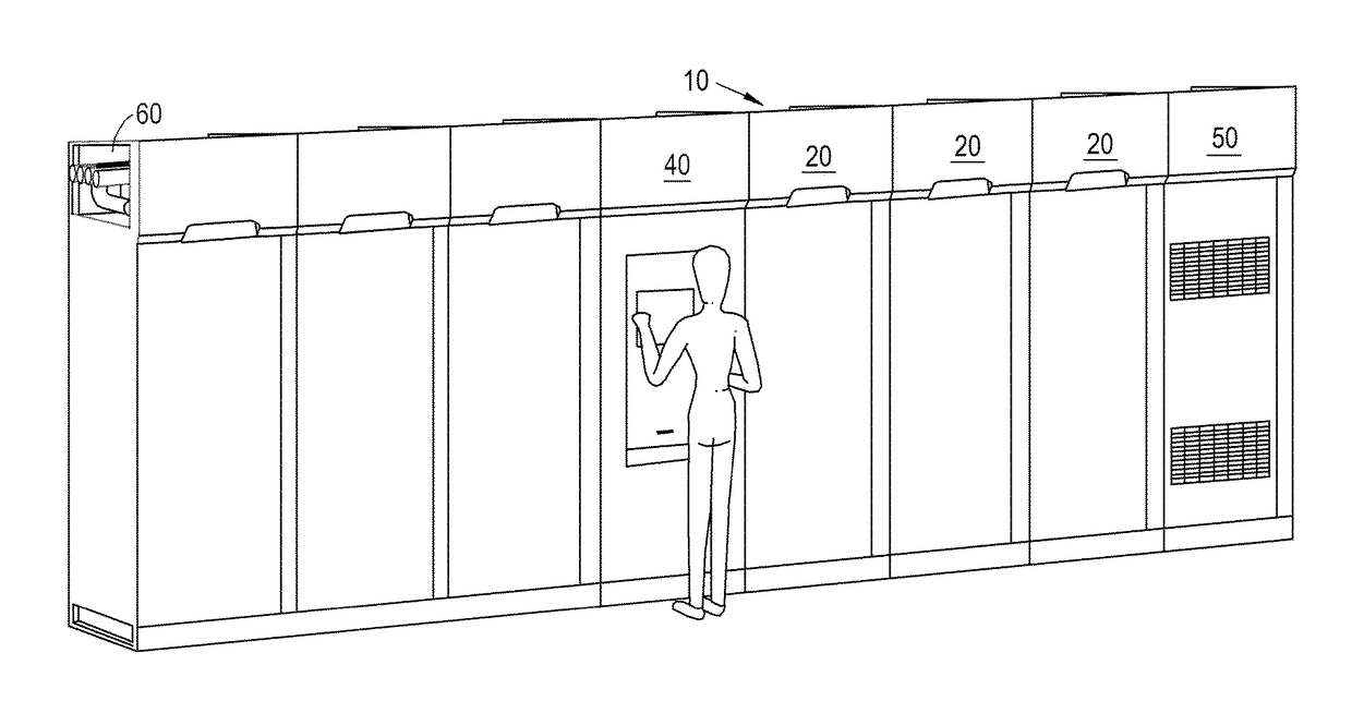
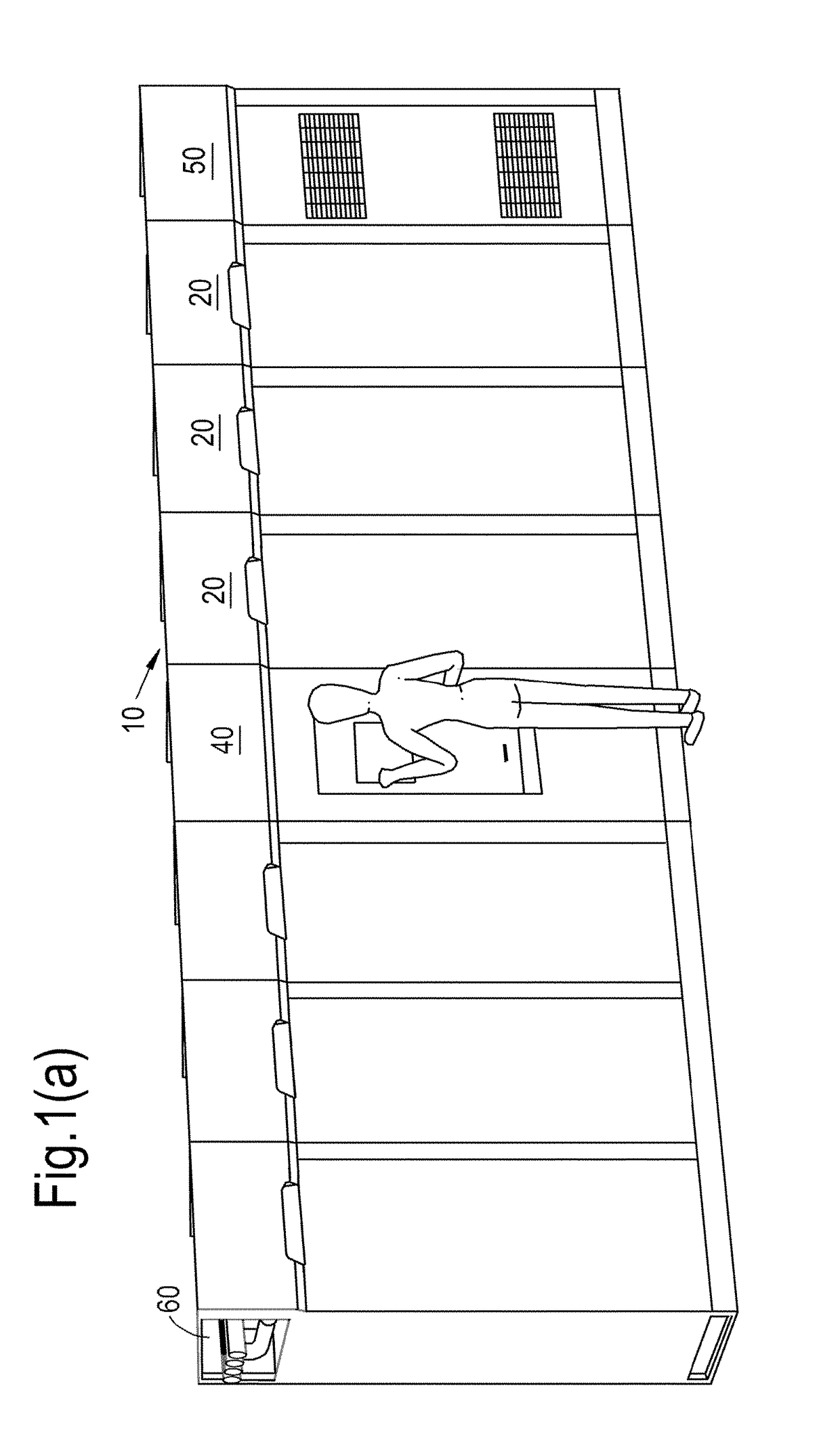
[0139]The apparatus 10 according to an embodiment of the present invention shown in FIG. 1 comprises a plurality of units representing refrigerated locker modules 20, an access control module 40 for controlling access to and monitoring the status of the locker modules and a refrigeration plant module 50 coupled to a distribution system 60. The distribution system 60 is shown running along the top of the apparatus 10, to circulate and distribute heat transfer fluid from the refrigeration plant module 50 to the rest of the apparatus 10. In the particular embodiment shown in FIG. 1(a), the plurality of locker modules 20, the access control module 40 and the refrigeration plant modules 50 are arranged side-by-side to conserve floor space. However, other arrangements of the units are permissible such as a vertically stacked arrangement. Each of the units representing the plurality of locker modules 20, access control module 40 and the refrigerated plant module 50 are arranged in modular ...


PUM


Abstract

A temperature controlled storage apparatus 8(10), comprising; a plurality of lockable storage spaces, each of the plurality of lockable storage spaces comprising one or more compartments; in which the temperature of each of the one or more compartments is independently controllable to provide either one of: chilled temperature; or frozen temperature; and wherein access to the storage space is remotely programmable.

Description

CROSS REFERENCE TO RELATED APPLICATION[0001]This application is related to and claims priority benefits from the following GB Patent Applications: 1) Application Number GB1401539.0, filed on 29 Jan. 2014, entitled Refrigeration System; 2) Application Number GB1401910.3, filed on 4 Feb. 2014, entitled A Locker System; 3) Application Number GB1405566.9, filed on 27 Mar. 2014, entitled A Locker System; 4) Application Number GB1411043.1, filed on 18 Jun. 2014, entitled A Locker System; 5) Application Number GB1416641.7, filed on 19 Sep. 2014, entitled A Locker System; 6) Application Number GB1416742.3, filed on 22 Sep. 2014, entitled A Locker System; 7) Application Number GB1423158.3, filed on 23 Dec. 2014, entitled A Locker System. The aforementioned patent applications are hereby incorporated in their entirety by these references.FIELD OF INVENTION[0002]The present invention relates to a locker system, more preferably to a refrigerated / heated locker system for the storage of perishabl...

Claims


Application Information

Patent Timeline
Patent Type & Authority Applications(United States)
IPC IPC(8): A47G29/14F25D29/00G07C9/00F25D13/04
CPCA47G29/141F25D13/04F25D29/00G07C9/00039A47G2200/166A47G2029/147A47G2029/149A47G2200/186F25D2600/02A47G29/14F25D13/02F25D23/10F25D23/12F25D29/003F25D2700/121F25D2500/06G07F17/13F25B5/02F25B29/003G07F9/105G07F11/62A47G29/30F25D3/04A47B88/90G07C9/23F25D25/00F25D25/02A23B4/06F25D13/00F25D17/00
Inventor DADE, NIGELHUNT, GARETHCHUNG, HOI KANIMAM, NASHIM
Owner ILLINOIS TOOL WORKS INC
Why Eureka
Try Eureka