
Signal processing method and imaging system for scatter correction in computed tomography

a computed tomography and processing method technology, applied in tomography, instruments, applications, etc., can solve problems such as degrading image quality and reducing image resolution

Active Publication Date: 2017-08-03
GENERAL ELECTRIC CO
View PDF5 Cites 2 Cited by
  • Summary
  • Abstract
  • Description
  • Claims
  • Application Information

AI Technical Summary

Benefits of technology

The patent text describes a method and system for detecting and estimating the intensity of X-rays passing through an object made of multiple materials. This is done by obtaining information about the materials and the way they absorb X-rays, and then using this information to estimate the intensity of the primary X-rays that have passed through the object. This technique can be used in various applications such as medical imaging and security screening. The technical effects of this patent are improved accuracy and efficiency in X-ray imaging and improved ability to detect and analyze X-rays from multiple materials.

Problems solved by technology

In a CT imaging system, scatter signal in the X-ray measurement can cause shading artifacts, reduce image resolution, and other artifacts which all degrade image quality.

Method used


Image

  • Signal processing method and imaging system for scatter correction in computed tomography
  • Signal processing method and imaging system for scatter correction in computed tomography
  • Signal processing method and imaging system for scatter correction in computed tomography

Examples


Embodiment Construction

[0013]Embodiments of the present disclosure will be described herein below with reference to the accompanying drawings. In the following description, well-known functions or constructions are not described in detail to avoid obscuring the disclosure in unnecessary detail.

[0014]Unless defined otherwise, technical and scientific terms used herein have the same meaning as is commonly understood by one of ordinary skill in the art to which this disclosure belongs. The terms “first”, “second”, “third” and the like, as used herein do not denote any order, quantity, or importance, but rather are used to distinguish one element from another. Also, the terms “a” and “an” do not denote a limitation of quantity, but rather denote the presence of at least one of the referenced items. The term “or” is meant to be inclusive and mean either or all of the listed items. The use of “including,”“comprising” or “having” and variations thereof herein are meant to encompass the items listed thereafter an...


PUM


Abstract

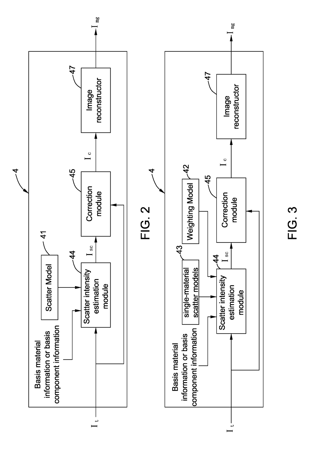
A signal processing method is disclosed, which includes detecting a total intensity of X-rays passing through an object comprising multiple materials; obtaining at least one set of basis information of basis material information of the multiple materials and basis component information of photon-electric absorption basis component and Compton scattering basis component of the object; estimating a scatter intensity component of the detected X-rays based on the at least one set of basis information and the detected total intensity; and obtaining an intensity estimate of primary X-rays incident on a detector based on the detected total intensity and the estimated scatter intensity component. An imaging system adopting the above signal processing method is also disclosed.

Description

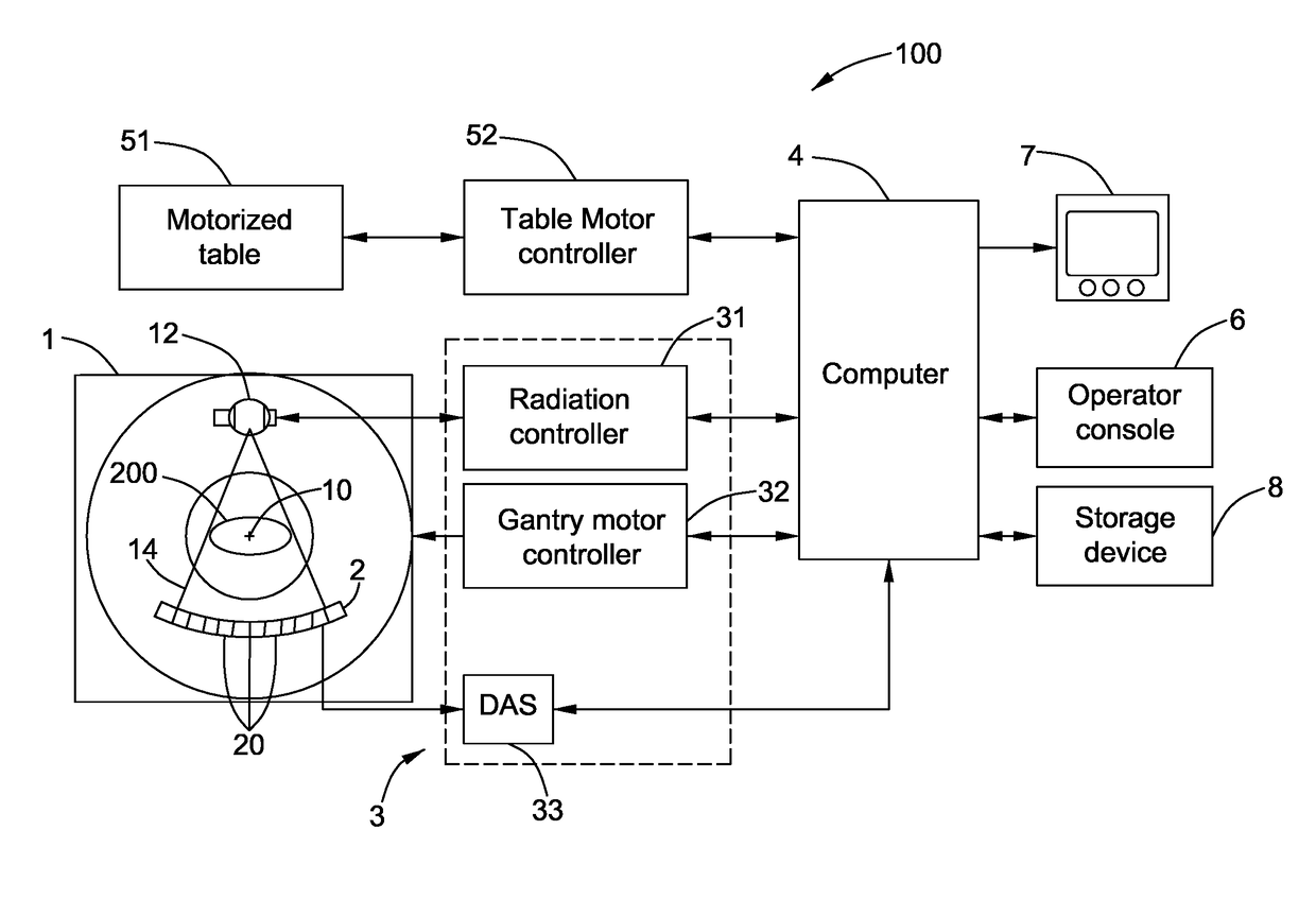
BACKGROUND[0001]This disclosure relates generally to a signal processing technique, and more particularly to a signal processing method and an imaging system for scatter correction in computed tomography.[0002]Non-invasive imaging technologies, such as computed tomography (CT), allow images of internal structures of an object to be obtained without performing an invasive procedure on the object. In a CT imaging system, scatter signal in the X-ray measurement can cause shading artifacts, reduce image resolution, and other artifacts which all degrade image quality. At the same time, the scatter signal from the object is one of the major sources of bias of the quantitative measurements from the reconstructed images of the CT imaging system.[0003]Accordingly, it would be desirable to reduce or eliminate the impact of scatter from the object that to be measured. Therefore, an improved scatter correction method would improve CT image quality.BRIEF DESCRIPTION[0004]In one embodiment, the p...

Claims


Application Information

Patent Timeline
IPC IPC(8): A61B6/00A61B6/03
CPCA61B6/5282A61B6/482A61B6/032A61B6/03A61B6/52A61B6/4241A61B6/50A61B6/5205
Inventor RUI, XUEWU, MINGYEJIN, YANNANEDIC, PETER MICHAELDE MAN, BRUNO KRISTIAAN BERNARD
Owner GENERAL ELECTRIC CO
Learn More