Test platform for high-frequency cable

a high-frequency cable and test platform technology, applied in the field of cable test systems, can solve the problems of unachievable complete test data, relative large cable structure, relative large damage to the cable structure, etc., and achieve the effect of shortening the strip length, improving the test frequency, and sufficient arrangement spa

Active Publication Date: 2017-08-03
SHANGHAI ELECTRIC CABLE RES INST +1
View PDF3 Cites 2 Cited by
  • Summary
  • Abstract
  • Description
  • Claims
  • Application Information

AI Technical Summary

Benefits of technology

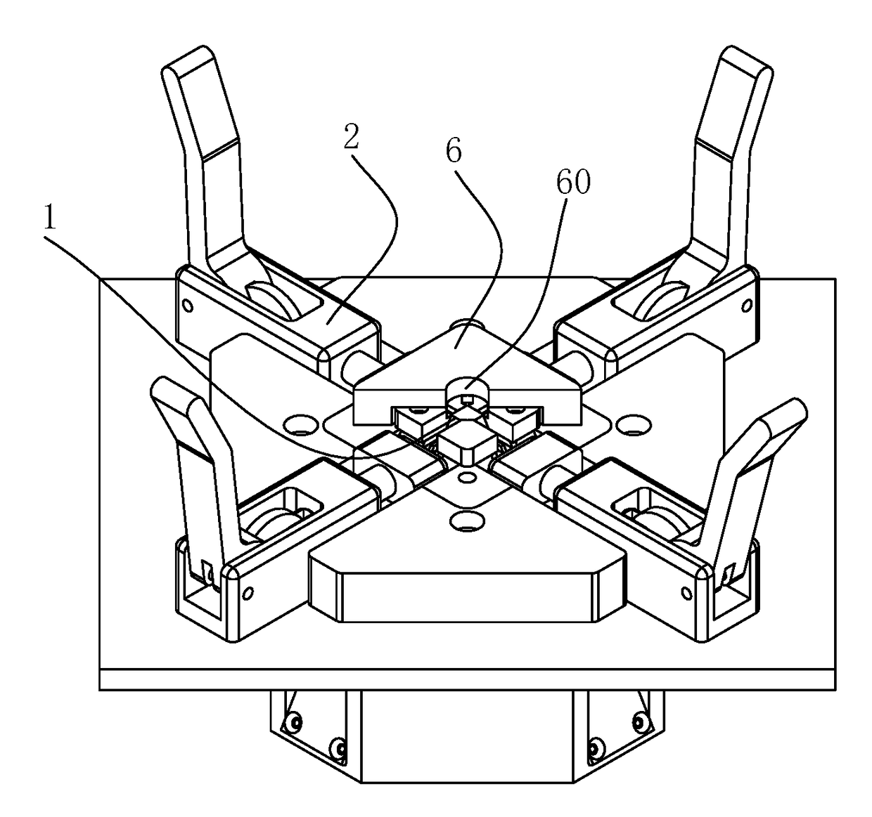
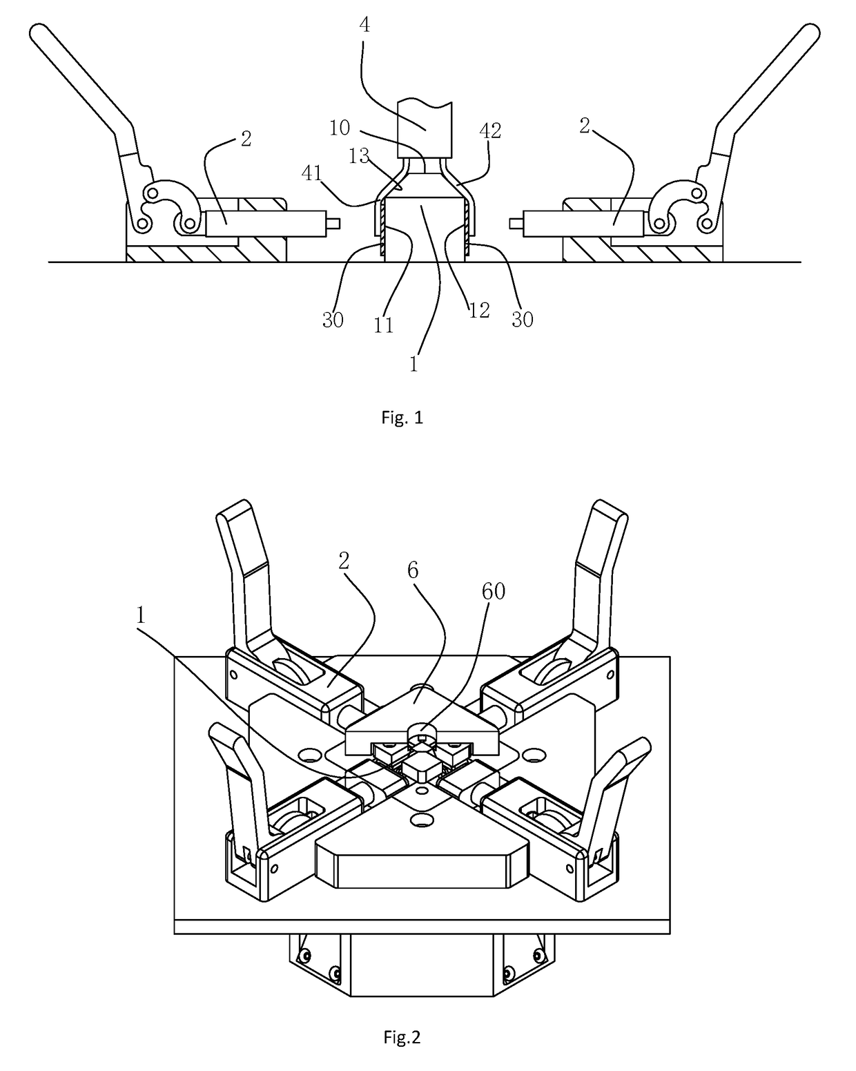
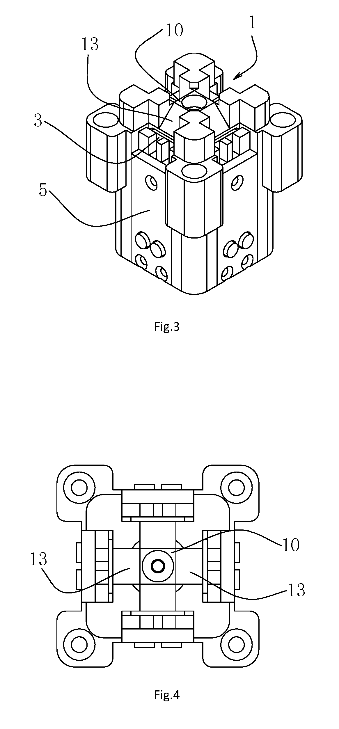
[0018]As comparing to the prior art, the present invention has significant beneficial effects that: firstly, the present invention adopts a splitter seat with a polyhedral structure, which may allocate the plurality pairs of cores to be tested to each side of the splitter seat to connect with the cable test system, for simultaneously performing test on the plurality pairs of cores; secondly, since each pair of cores is located at a different side of the splitter seat, as such, each pair of cores keeps a relative focus state on the splitter seat, and each clamp may still have sufficient arrangement space in the periphery of the splitter seat, with the result that, during the wiring in the present invention, there is no need for a very long stripped length, and the shortening of the stripped length is beneficial for the improvement of the test frequency; thirdly and particularly advantageously, an inclined splitter channel is provided between the top surface and side of the splitter seat of the present invention, which may shorten the stripped length on one hand, and prevent vertically bending the core on the other hand, as a result, the present invention may reduce the damage to the cable structure to the greatest extent during wiring, and greatly increase the test frequency, e.g., the present invention may increase the cable test frequency above 2.4 GHz.

Problems solved by technology

As for high band test, test is either performed on a pair of core each time, or simultaneously performed on multiple pairs of cores at a relative low frequency, wherein, for the former one, the mutual crosstalk among multiple pairs of cores fails to test in this way; and for the latter one, when simultaneously testing the multiple pairs of cores, complete test data is still unachievable, because outer cladding of the symmetric data cable is excessively broken by the wiring process.
Such structure may shorten the stripped length of the cable, however, since the core is vertically bended, the damage to the cable structure is relative large, and thus the test frequency thereof is just about 1.2 GHz.
In view of foregoing, regarding to the cable test system in the prior art, since all the cores are arranged in a same plane for testing, the damage to the cable structure is relative large, and thus it may not meet the test requirement of higher frequency.

Method used


Image

  • Test platform for high-frequency cable
  • Test platform for high-frequency cable
  • Test platform for high-frequency cable

Examples


Embodiment Construction

[0026]Hereinafter, the detailed description of the present invention will be illustrated in details with reference to figures. Those embodiments are merely used to describe the present invention, but not to limit the invention.

[0027]In the description of the invention, it should be noted that, the indicated orientation or positional relationship, e.g., terms of “center”, “upper”, “lower”, “vertical”, “horizontal”, “top”, “bottom”, “inner”, “outer”, etc., are based on the indicated orientation or positional relationship as shown in figures, and are merely used for ease of description and simplicity, but not for indicating or implying the specific orientation of the device or means meant to be, or the specific configured orientation and operation, and thus should not be construed as the limitation of the present invention. In addition, the ordinal numbers of “first”, “second”, etc., are merely used for ease of description, and should not be construed to indicate or imply the relative ...


PUM


Abstract

The present invention discloses a test platform for high-frequency cable, comprising conductive contacts and clamps for pressing a conductor of the cable on the conductive contact, and comprising a splitter seat, which comprises a top surface and a plurality of varied sides, the conductive contacts are respectively arranged on the sides, the clamps are arranged at a peripheral of the splitter seat and is opposite to the conductive contact, the splitter seat is further provided with a splitter channel, and the splitter channel slantingly connects the top surface to the sides. The present invention adopts a splitter seat with a polyhedral structure, which may shorten the stripped length, and prevent for vertically bending the core, thereby reducing the damage to the cable structure to the greatest extent, and greatly increasing the test frequency.

Description

BACKGROUND OF THE PRESENT INVENTION[0001]Field of Invention[0002]The present invention relates to a cable test system, and particularly relates to a test platform for a high-frequency cable.[0003]Description of Related Arts[0004]Generally, a cable contains several pairs of cores, when performing cable test, it is required to strip the cable to expose a conductor of each core at the end, then those cores are accessed to the cable test system via a connection apparatus to perform the test. The higher the test frequency is, the shorter the required stripped length of the cable is, as well as the higher the requirement for the integrity of the cable structure itself is. As such, when performing high frequency test, advanced requirement is presented on the test platform for the high-frequency cable.[0005]Conventional symmetric data cable tests are mainly concentrated at lower bands (mainly 1˜350 MHz, 1˜750 MHz). As for high band test, test is either performed on a pair of core each time,...

Claims


Application Information

Patent Timeline
Patent Type & Authority Applications(United States)
IPC IPC(8): G01R31/02G01R1/04
CPCG01R1/0416G01R31/021G01R1/0408G01R31/58
Inventor ZHANG, CHENGJIANG, BINSHEN, NALLIANGONG, JIANGJIANGYIN, YING
Owner SHANGHAI ELECTRIC CABLE RES INST
Why Eureka
Try Eureka