Solar cell panel

a solar cell and panel technology, applied in the field of solar cell panels, can solve the problems of increasing the cost of installing the insulating barrier, the weight of prior art solar cell panels, and the increase in the cost of solar cell panels. achieve the effect of adequate safety margin

Inactive Publication Date: 2017-08-03
MITSUBISHI ELECTRIC CORP
View PDF2 Cites 1 Cited by
  • Summary
  • Abstract
  • Description
  • Claims
  • Application Information

AI Technical Summary

Benefits of technology

[0013]As a result, electric discharges can be prevented from occurring between any solar cells in the solar cell panel without installing an insulating barrier into the gap between any solar cells. In addition, when installing an insulating barrier into the gap between any solar cells, a more adequate margin of safety can be provided against electric discharges between solar cells as compared with prior art solar cell panels.

Problems solved by technology

The first problem is that the prior art solar cell panel increases in weight by only the weight of the adhesive which is used as the insulating barrier.
The second problem is that the prior art solar cell panel increases in cost because of increase in the material cost of the adhesive which is used as the insulating barrier, the cost of installing the insulating barrier, increase in the cost of launching a rocket, and so on.
The uppermost ends of any two adjacent solar cell assembly series having the maximum potential difference are at increased risk of causing electrostatic discharges.

Method used


Image

  • Solar cell panel
  • Solar cell panel
  • Solar cell panel

Examples


embodiment 1

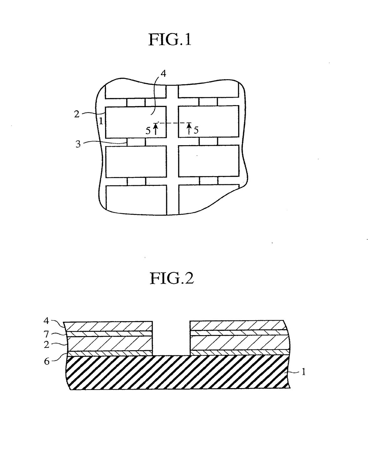
[0021]FIG. 1 is a plan view showing embodiment 1 of the present invention. In FIG. 1, solar cells 2 are secured to a surface of an insulator 1. Interconnectors 3 are connected to each of the solar cells 2, and a cover glass 4 is bonded to each of the solar cells 2.

[0022]FIG. 2 is a cross-sectional view showing a cross section of FIG. 1 taken along the line 5-5.

[0023]As shown in FIG. 2, each solar cell 2 is secured to the surface of the insulator 1 by an adhesive 6, and the cover glass 4 is secured to the light receiving surface of each solar cell 2 by an adhesive 7.

[0024]In FIGS. 1 and 2, wiring for connecting among solar cell assembly series is not shown.

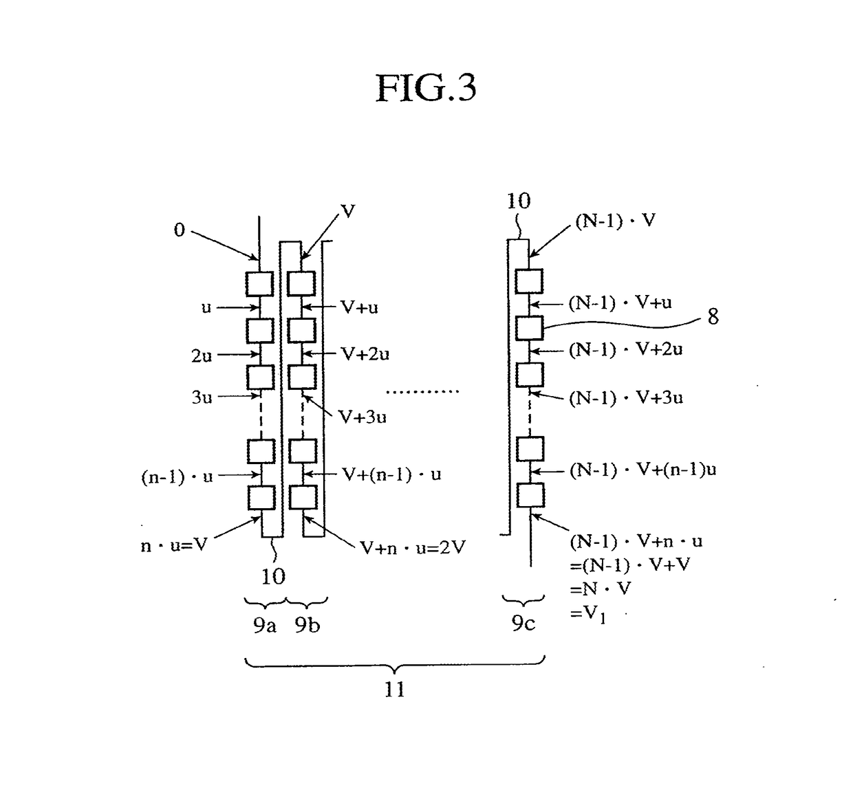
[0025]FIG. 3 is a diagram showing the structure of solar cell circuitry according to embodiment 1 of the present invention.

[0026]In FIG. 3, n solar cell assemblies 8 each having a maximum output voltage u are arranged substantially in a line so that each solar cell assembly series 9 is constructed. Each solar cell assembly series 9...

embodiment 2

[0030]FIG. 1 is a plan view showing embodiment 2 of the present invention. FIG. 2 is a cross-sectional view showing a cross section of FIG. 1 taken along the line 5-5.

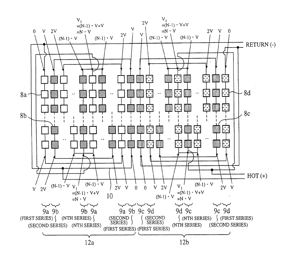
[0031]FIG. 4 is a diagram showing solar cell circuitry according to embodiment 2 of the present invention.

[0032]In FIG. 4, n solar cell assemblies 8a each having a maximum output voltage u are arranged substantially in a line so that each solar cell assembly series 9a is constructed. Each solar cell assembly series 9a has a maximum output voltage V=n*u.

[0033]Furthermore, N solar cell assembly series 9a are electrically connected in series byway of connection lines 10 so that a solar cell string 11a is constructed. Similarly, n solar cell assemblies 8b each having a maximum output voltage u are arranged substantially in a line so that each solar cell assembly series 9b is constructed. Each solar cell assembly series 9b has a maximum output voltage V=n*u.

[0034]Furthermore, N solar cell assembly series 9b are electrically...

embodiment 3

[0039]FIG. 1 is a plan view showing embodiment 3 of the present invention. FIG. 2 is a cross-sectional view showing a cross section of FIG. 1 taken along the line 5-5.

[0040]FIG. 5 is a diagram showing solar cell circuitry according to embodiment 3 of the present invention.

[0041]In FIG. 5, n solar cell assemblies 8a each having a maximum output voltage u are arranged substantially in a line so that each solar cell assembly series 9a is constructed. Each solar cell assembly series 9a has a maximum output voltage V=n*u. Furthermore, N solar cell assembly series 9a are electrically connected in series by way of connection lines 10 so that a solar cell string 11a is constructed.

[0042]Similarly, n solar cell assemblies 8b each having a maximum output voltage u are arranged substantially in a line so that each solar cell assembly series 9b is constructed. Each solar cell assembly series 9b has a maximum output voltage V=n*u. Furthermore, N solar cell assembly series 9b are electrically con...


PUM


Abstract

A plurality of solar cell assembly series 9 of a solar cell panel are so arranged that any two adjacent solar cells in the plurality of solar cell assembly series 9 have a potential difference which does not exceed V volts which is a maximum output voltage of the plurality of solar cell assembly series 9. Electric discharges between any two adjacent solar cells can be prevented from occurring. Even when the output voltage of a solar cell module changes according to control by a power control circuit, electric discharges can be prevented from occurring between solar cell modules in the solar cell array in which any two adjacent solar cells in the plurality of solar cell assembly series 9 always have a potential difference which does not exceed V volts which is the maximum output voltage of the plurality of solar cell assembly series 9. In addition, the solar cell modules can be constructed of a combination of solar cell series patterns having line symmetry. In this case, while electric discharges can be prevented from occurring between any solar cells, the magnetic field caused by the solar cell circuitry can be reduced.

Description

CROSS-REFERENCE TO RELATED APPLICATION[0001]This application is a continuation of U.S. patent application Ser. No. 10 / 508,539, filed Sep. 27, 2004, which is the U.S. National Stage Application of PCT International Application No. PCT / JP04 / 01200, filed Feb. 5, 2004, which claims priority to Japanese Patent Application No. 2003-033735, filed Feb. 12, 2003. The entire contents of each of the above applications are incorporated herein by reference in entirety.Field of the Invention[0002]The present invention relates to a solar cell panel for use in spacecrafts, such as satellites and airships. More particularly, it relates to a solar cell array and a solar cell panel structure that can prevent electrical discharges from occurring between any solar cells.BACKGROUND OF THE INVENTION[0003]In the past, many spacecrafts carrying a solar cell panel have been lofted into space. As spacecrafts become more sophisticated in functionality, solar cell panels which can supply high power to spacecraf...

Claims


Application Information

Patent Timeline
Patent Type & Authority Applications(United States)
IPC IPC(8): H01L31/05H01L31/0216H01L25/00H01L31/04H02N6/00
CPCH01L31/02167H01L31/0508Y02E10/50H01L31/0504
Inventor KOAKUTSU, HIDEAKI
Owner MITSUBISHI ELECTRIC CORP
Why Eureka
Try Eureka