Pouring nozzle and assembly of such a pouring nozzle with an inner nozzle

a technology of pouring nozzle and inner nozzle, which is applied in the direction of packaging, manufacturing converters, liquid dispensing, etc., can solve the problems of nozzle not being used for continuous casting of molten steel, raising a serious security concern, and risk of leakage, so as to reduce the disturbance of the flow of steel

Inactive Publication Date: 2014-12-09
VESUVIUS GRP SA
View PDF9 Cites 1 Cited by
  • Summary
  • Abstract
  • Description
  • Claims
  • Application Information

AI Technical Summary

Benefits of technology

[0019]By virtue of this particular configuration of the orifice of the pouring channel in the top surface of the plate, it is possible to close off the pouring channel very rapidly by making the pouring nozzle slide so that part of the plate not having an orifice comes in line with the orifice of the pouring channel formed in the bottom end of the inner nozzle. For an identical pouring cross section of the orifice of the pouring channel, the shape of the orifice of the pouring channel reduces the distance to be travelled by the nozzle in order to pass from a total opening position to a total closure position. Consequently, at equal movement speeds and with identical cross sections, the closure of the pouring channel will be effected more rapidly than for a nozzle with a circular orifice as described above. The operator thus saves precious time for interrupting the pouring.
[0020]In addition, the fault that had led to the commercial rejection of the previous system, namely the need to extend the plate of the pouring nozzle and consequently the stroke of the jack and, ultimately, the bulk of the device, is greatly minimised since the oblong shape of the orifice does not require significant extension of the plate.
[0021]Advantageously, the major axis of the oblong orifice is off centre with respect to the sides of the rectangle perpendicular to the axis of the outlets. In this way the use of the surface of the plate is optimised. It is thus possible to close off the pouring channel even with a plate of reduced size. Generally, the plate is sized so as to leave sufficient safety margin between the pouring orifice and the periphery of the plate, between the pouring orifice and the area of the plate intended to close off the orifice in the inner nozzle and between this closure area and the periphery. In particular, it is recommended to leave a minimum distance of approximately 30 mm, preferably 40 mm, or even 50 mm between the periphery of the pouring orifice and the periphery of the plate. This distance may be less between the periphery of the orifice and the sides of the plate parallel to the axis of the outlets since the thrust exerted by the supplying and exchanging device (in particular the guide rails) on the pouring nozzle is generally distributed along its sides close to the pouring orifice. Thus a safety distance of 20 to 30 mm may suffice. Likewise, it will be sufficient to leave 5 to 20 mm between the pouring orifice and the area of the plate intended to close off the orifice in the inner nozzle and between this closure zone and the periphery. The plate itself will have to have a dimension in the direction corresponding to the outlet axis equal to twice the dimension of the minor axis of the orifice (in order to accept therein the pouring orifice and the closure area) increased by the safety margins. Advantageously, this dimension of the plate will therefore be at least three times the dimension of the minor axis of the orifice.
[0024]A study of the flow by the finite elements method has determined that it is highly advantageous to effect the transition very abruptly close to the inlet orifice of the pouring channel in the nozzle. According to the invention, the pouring channel passes abruptly (e.g., over a distance of between 20 and 50 mm as from the top surface of the upstream plate of the nozzle) from an oblong cross section to a circular cross section. The effect of this abrupt change is to partially compensate for the pressure drop caused by the passage of the steel through the pouring nozzle and which would tend to suck air through the surface joint between the inner nozzle and the pouring nozzle.
[0025]Preferably, the inner nozzle, which is the part directly upstream of the pouring nozzle according to the present invention, has an outlet orifice conformed so as to be substantially identical to the inlet orifice of the pouring channel in the nozzle in order to minimise disturbance to the flow of steel at the interface between these two pouring elements. Another object of the invention therefore relates to an assembly of the pouring nozzle according to the present invention and an inner nozzle, the inner nozzle comprising a plate at one end, referred to as the downstream end, provided with a discharge orifice, the seal between the pouring nozzle and the inner nozzle being effected by joining the downstream plate of the inner nozzle and the upstream plate of the pouring nozzle. According to this aspect of the invention, the discharge orifice of the inner nozzle is conformed in a substantially identical manner to the inlet orifice of the pouring channel in the pouring nozzle, so that, in the pouring position, the two orifices fluidly communicate.

Problems solved by technology

Such a nozzle could not be used for the continuous casting of molten steel from a tundish into a continuous casting mould.
Indeed, the uncooled steel jet continuously emerging from the nozzle end portion and directly plunging towards the bottom end of the ingot mould would raise a serious security concern (risk of leakage).

Method used


Image

  • Pouring nozzle and assembly of such a pouring nozzle with an inner nozzle
  • Pouring nozzle and assembly of such a pouring nozzle with an inner nozzle

Examples


Embodiment Construction

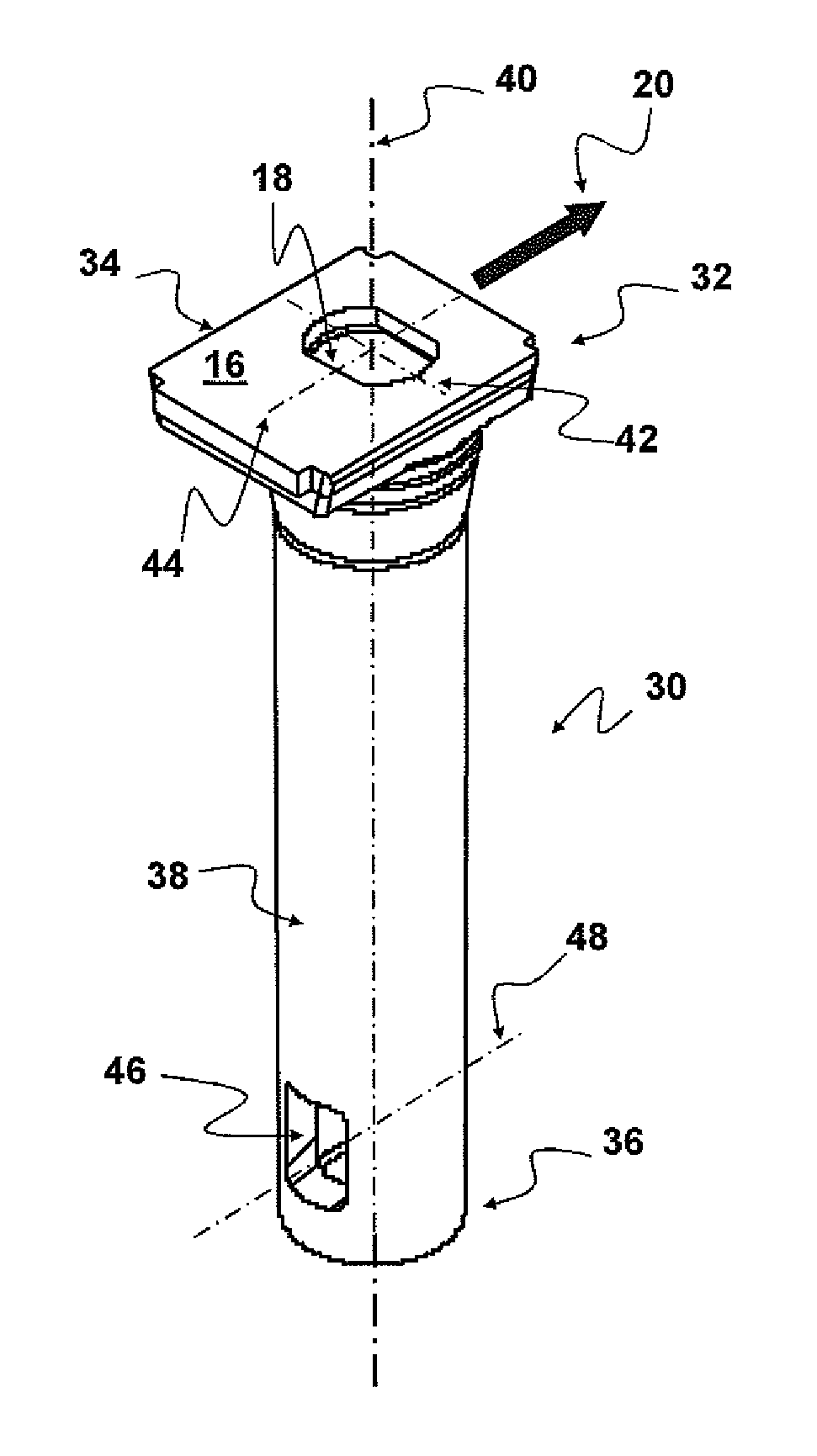
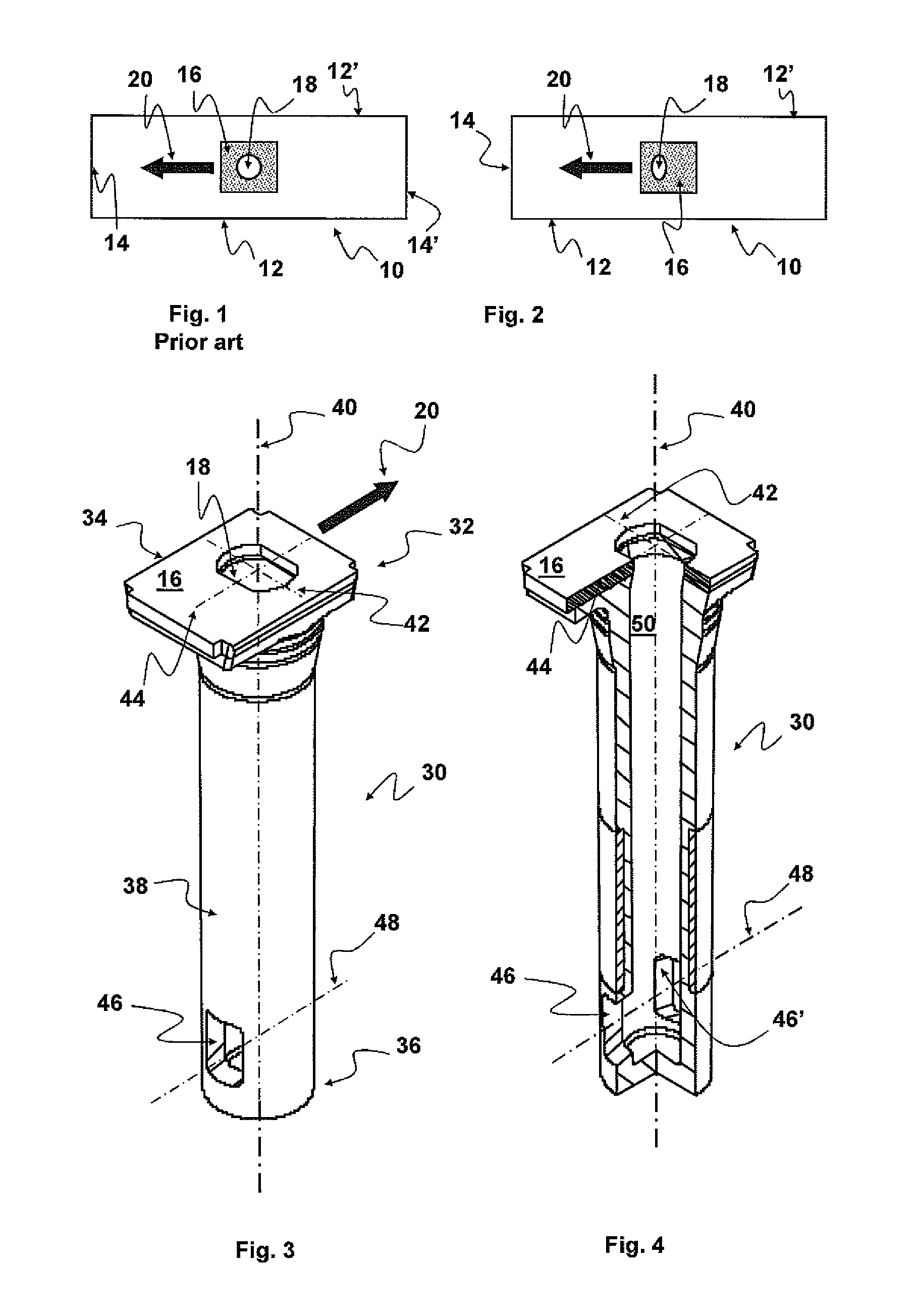
[0031]An ingot mould 20, roughly rectangular in shape, having two long sides 12, 12′ and two small sides 14, 14′, can be seen schematically in FIGS. 1 and 2. At the centre of the ingot mould a pouring nozzle seen from above is shown, only the top surface 16 of which provided with a pouring orifice 18 can be seen. The details of the supplying and exchanging device are not visible in these figures. The direction 20 of sliding of the pouring nozzle in the nozzle supplying and exchanging device are also shown in each ingot mould. It will be noted that the discharge orifices of the pouring nozzle shown in FIGS. 1 and 2 are aligned in a direction parallel to the direction of sliding 20. Whereas the pouring orifice 18 of the nozzle known from the prior art (FIG. 1) is circular and centred with respect to the top surface 16, the pouring orifice 18 of the pouring nozzle according to the invention (FIG. 2) has an oblong shape. The orifice is elongate in a direction perpendicular to the direct...


PUM

PropertyMeasurementUnit
distanceaaaaaaaaaa
distanceaaaaaaaaaa
distanceaaaaaaaaaa

Abstract

A pouring nozzle includes a generally rectangular shaped plate and a tube extending from the bottom surface of the plate. The nozzle includes a pouring channel emerging close to the downstream end of the tube through outlets formed in the lateral walls of the tube. The outlets are disposed symmetrically on either side of the axis of the tube. The axis of the outlets is substantially parallel to a pair of sides of the plate. The orifice is oblong and has a major axis and a minor axis. The minor axis of the orifice is parallel to the axis of the outlets. The pouring nozzle may be assembled with an inner nozzle. This nozzle and its assembly with an inner nozzle may be used for the continuous casting of steel from a tundish towards a continuous casting mould.

Description

BACKGROUND OF THE INVENTION[0001](1) Field of the Invention[0002]The present invention relates to a refractory element used for the continuous casting of molten steel from an upstream metallurgical vessel to a downstream metallurgical vessel.[0003]According to a particular embodiment of the invention, the nozzle is used for casting molten steel from a distribution tank (sometimes also called a tundish) to a casting mould or ingot mould (sometimes also called a coquille).[0004](2) Description of Related Art[0005]In the continuous casting of steel from the tundish to an ingot mould, a pouring nozzle is used to protect the liquid steel from chemical attacks from the surrounding atmosphere and to isolate it thermally during its transfer from the upstream vessel to the downstream vessel. These nozzles, roughly cylindrical in shape, consist of a single piece having an upstream end possessing a generally tapered inlet disposed in the vicinity of the bottom of the upstream vessel. These noz...

Claims


Application Information

Patent Timeline
Patent Type & Authority Patents(United States)
IPC IPC(8): B22D41/22B22D41/50
CPCB22D41/50B22D41/22
Inventor SIBIET, FABRICE
Owner VESUVIUS GRP SA
Why Eureka
Try Eureka