Leakage current detection device for appliances

a leakage current detection and detection device technology, applied in the direction of emergency protective arrangements for limiting excess voltage/current, electrical devices, and arrangements responsive to excess current, can solve the problems of inability to ensure that the leakage current circuit interrupter will function normally, loss of protection function of the circuit interrupter, and loss of plug protection function, etc., to achieve the effect of improving the protection function of the leakage current detection devi

Active Publication Date: 2017-08-03
LI CHENGLI
View PDF5 Cites 13 Cited by
  • Summary
  • Abstract
  • Description
  • Claims
  • Application Information

AI Technical Summary

Benefits of technology

[0029]In summary, leakage current detection device uses the relay holding unit to maintain connection between the power source and the load, uses leakage current detection unit to monitor the operation of the power lines, uses the self-testing unit to monitor the operat

Problems solved by technology

However, in practice, not all users follow the advice of testing the device before use, so often it cannot be ensured that the leakage current circuit interrupter will function normally before it is put to use.
Further, even if the user tested the leakage current circuit interrupter device before use, during use, the protection function of the circuit interrupter may be lost (take the example of an electrical water heater with a leakage current detection

Method used


Image

  • Leakage current detection device for appliances
  • Leakage current detection device for appliances
  • Leakage current detection device for appliances

Examples


first embodiment

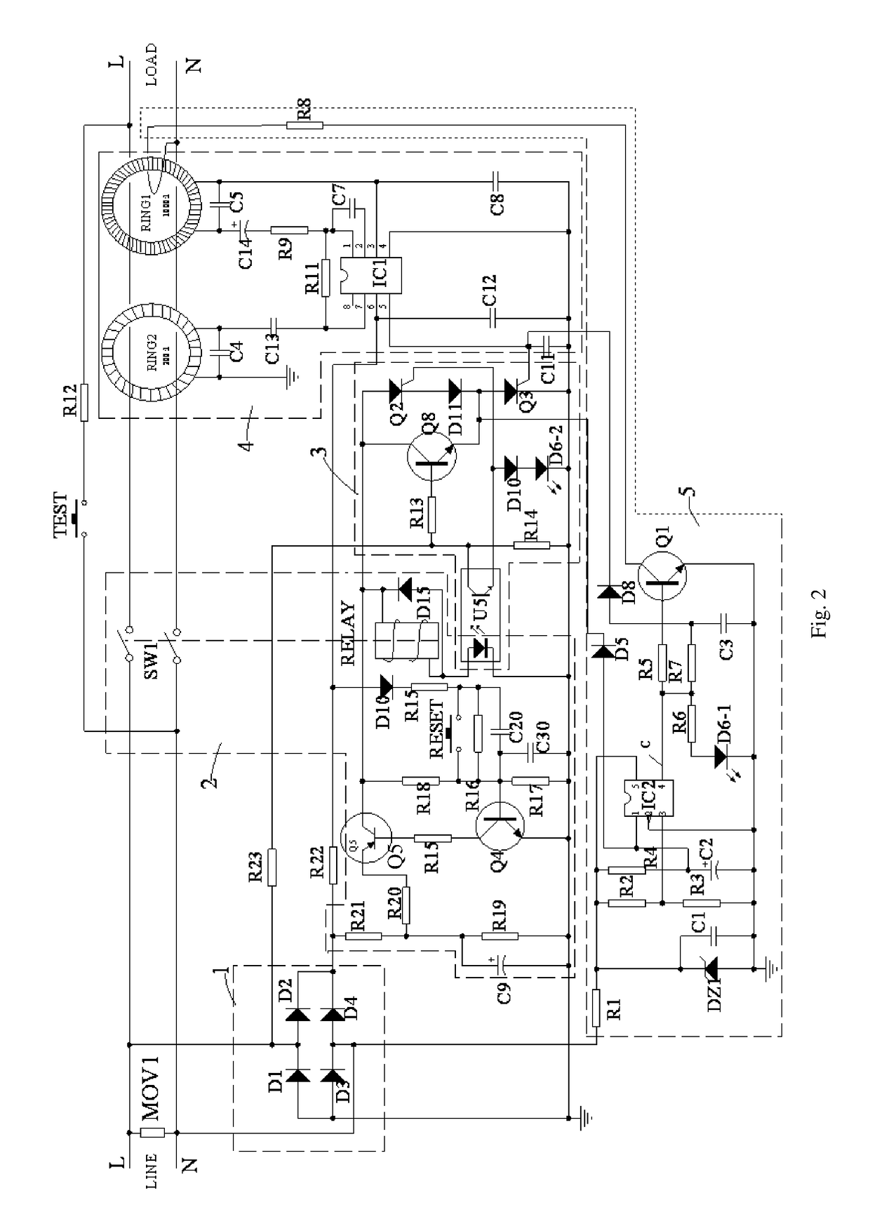
[0045]FIG. 2 is a circuit diagram of a leakage current detection device according to the present invention.

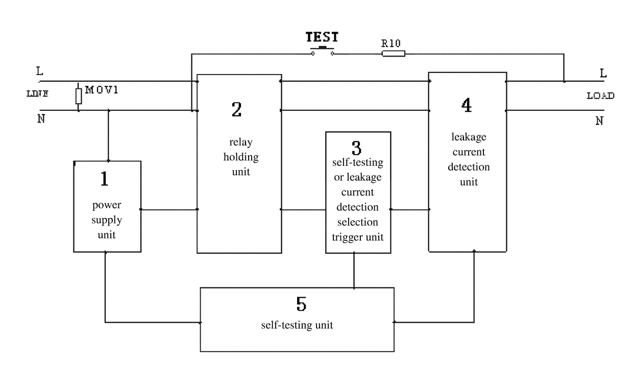
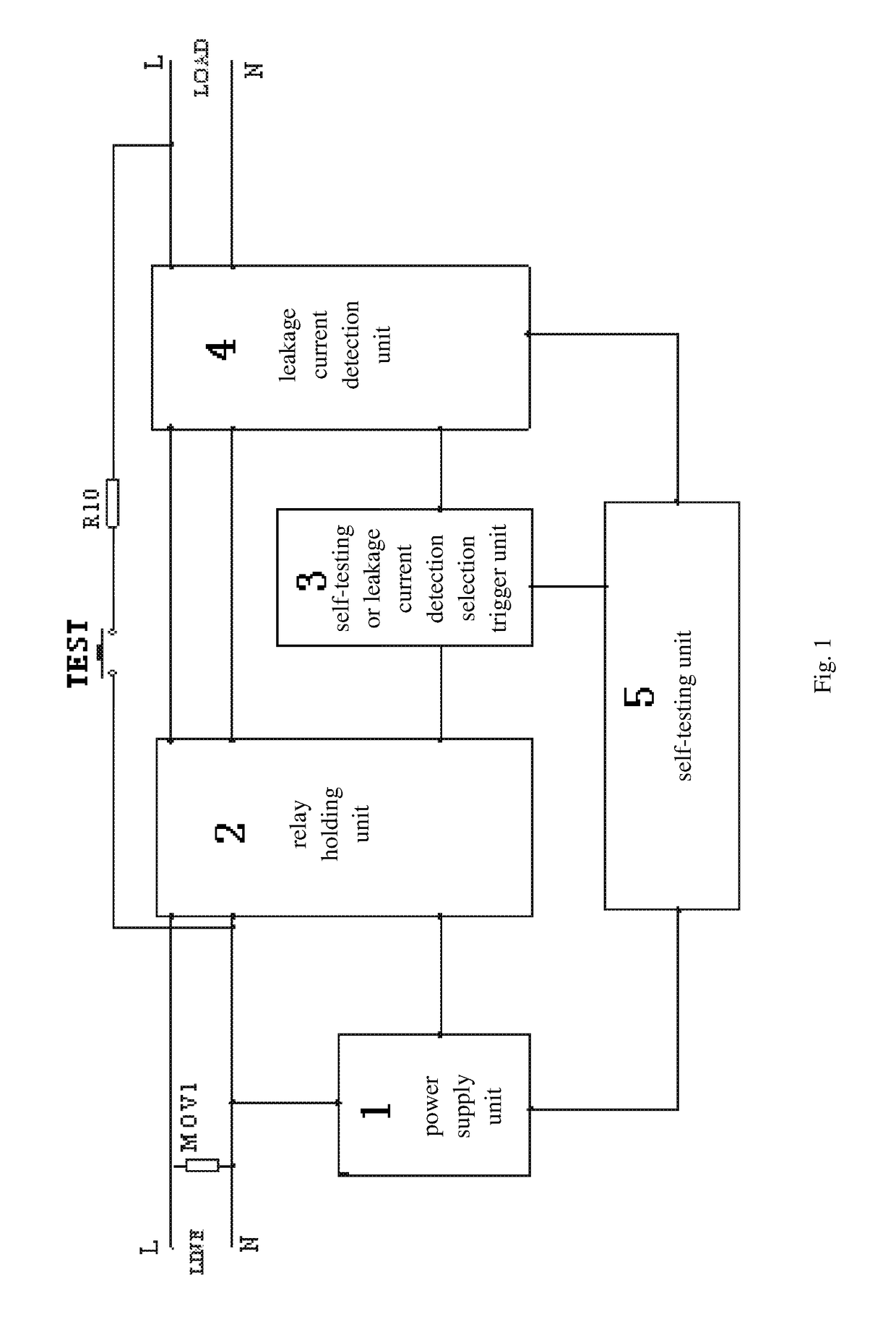
[0046]As shown in FIG. 2, the relay holding unit 2 includes at least: reset switch RESET, second transistor Q4, third transistor Q5, resistor R18, relay coil and relay switch SW1, connected in the manner shown in FIG. 2.

[0047]The self-testing or leakage current detection selection trigger unit 3 includes at least: first SCR (silicon controller rectifier) Q2, second SCR Q3, fifth transistor Q8, and first fault indicator unit D6-2, connected in the manner shown in FIG. 2.

[0048]The leakage current detection unit 4 includes at least: processor IC1 and detection coils, connected in the manner shown in FIG. 2.

[0049]The self-testing unit 5 includes at least: compactor IC2, second fault indicator unit D6-1, first transistor Q1, multiple resistors R1 to R8 and multiple capacitors C1 to C3, connected in the manner shown in FIG. 2.

[0050]The operation of the various units when detecting le...

second embodiment

[0078]FIG. 3 is a circuit diagram of a leakage current detection device according to the present invention.

[0079]Compared to the embodiment of FIG. 2, in the embodiment of FIG. 3, the relay holding unit is replaced by an auxiliary switch linked to the relay switch. This reduces the use of electrical components and improves the life and reliability of the device.

[0080]Also, similar to the embodiment of FIG. 2, when the reset switch is closed, the relay is energized and actuated, and the auxiliary switch K and relay switch SW1 are closed; the relay is self-latched by the auxiliary switch K and operates normally, so the load side is connected to the line side.

[0081]In the embodiment of FIG. 3, the self-testing and leakage current detection functions as well as the normal and abnormal situations are similar to those in the embodiment of FIG. 2 and detailed descriptions are omitted here.

third embodiment

[0082]FIG. 4 is a circuit diagram of a leakage current detection device according to the present invention.

[0083]As shown in FIG. 4, the relay holding unit 2 includes at least: second transistor Q4, third transistor Q5, multiple resistors R18 to R20, relay coil, relay switch SW1, and first fault indicator unit D6-2, connected in the manner shown in FIG. 4.

[0084]The self-testing or leakage selection trigger unit 3 includes at least: fourth transistor Q7, second SCR Q3, fifth transistor Q8, reset switch RESET, and resistor R23, connected in the manner shown in FIG. 4.

[0085]The leakage current detection unit 4 includes at least: processor IC1 and detection coils, connected in the manner shown in FIG. 4.

[0086]The self-testing unit 5 includes at least: comparator IC2, second fault indicator unit D6-1, first transistor Q1, multiple resistors R1 to R8 and multiple capacitors C1 to C3, connected in the manner shown in FIG. 4.

[0087]Referring to FIG. 4, the operations of the selection trigger...


PUM


Abstract

A leakage current detection device connected between a power source and a load, which includes a self-testing or leakage current detection selection trigger unit, for selecting a leakage current detection mode or a self-testing mode; a self-testing unit, for periodically generating a simulated leakage current signal in the self-testing mode; and a leakage current detection unit, for detecting a leakage current signal in the leakage current detection mode and detecting the simulated leakage current signal in the self-testing mode. The selection trigger unit further causes the power source to be disconnected from the load when a leakage current signal is detected, and sends a self-testing result to the self-testing unit depending on whether the leakage current detection unit detects the simulated leakage current signal. The self-testing unit displays an indication of the self-testing result.

Description

BACKGROUND OF THE INVENTION[0001]Field of the Invention[0002]This invention relates to electrical circuits for appliances, and in particular, it relates to a leakage current detection device.[0003]Description of Related Art[0004]With the wide use of electrical appliances, safety in their use is important. Leakage current detection devices with circuit interrupter functions are widely used. However, in practice, not all users follow the advice of testing the device before use, so often it cannot be ensured that the leakage current circuit interrupter will function normally before it is put to use. Further, even if the user tested the leakage current circuit interrupter device before use, during use, the protection function of the circuit interrupter may be lost (take the example of an electrical water heater with a leakage current detection and interruption plug, the plug may lose its protection function during use if some parts are damaged). In such a situation, when the appliance h...

Claims


Application Information

Patent Timeline
IPC IPC(8): H02H3/02
CPCH02H3/02H02H3/05H02H3/335
Inventor LI, CHENGLIYUE, GUOLANZHANG, WEI
Owner LI CHENGLI
Why Eureka
Try Eureka