Four wheel vehicle

a four-wheel drive, vehicle technology, applied in the direction of vehicle sub-unit features, vehicle propulsion by batteries/cells, and passenger/occupant safety arrangements, etc., can solve the problems of insufficient space above the power unit for the installation of rear seats or luggage storage space, undesirable wide width of the vehicle body, and limited space for accommodating the battery unit. achieve the effect of preventing adversely affecting the electronic control uni

Active Publication Date: 2017-08-10
HONDA MOTOR CO LTD
View PDF5 Cites 19 Cited by
  • Summary
  • Abstract
  • Description
  • Claims
  • Application Information

AI Technical Summary

Benefits of technology

[0019]Thereby, the heat generated in the electric power conversion unit is favorably removed by

Problems solved by technology

In the former case, the space above the power unit is not available for the installation of a rear seat or a luggage storage space.
In

Method used


Image

  • Four wheel vehicle
  • Four wheel vehicle
  • Four wheel vehicle

Examples


Embodiment Construction

)

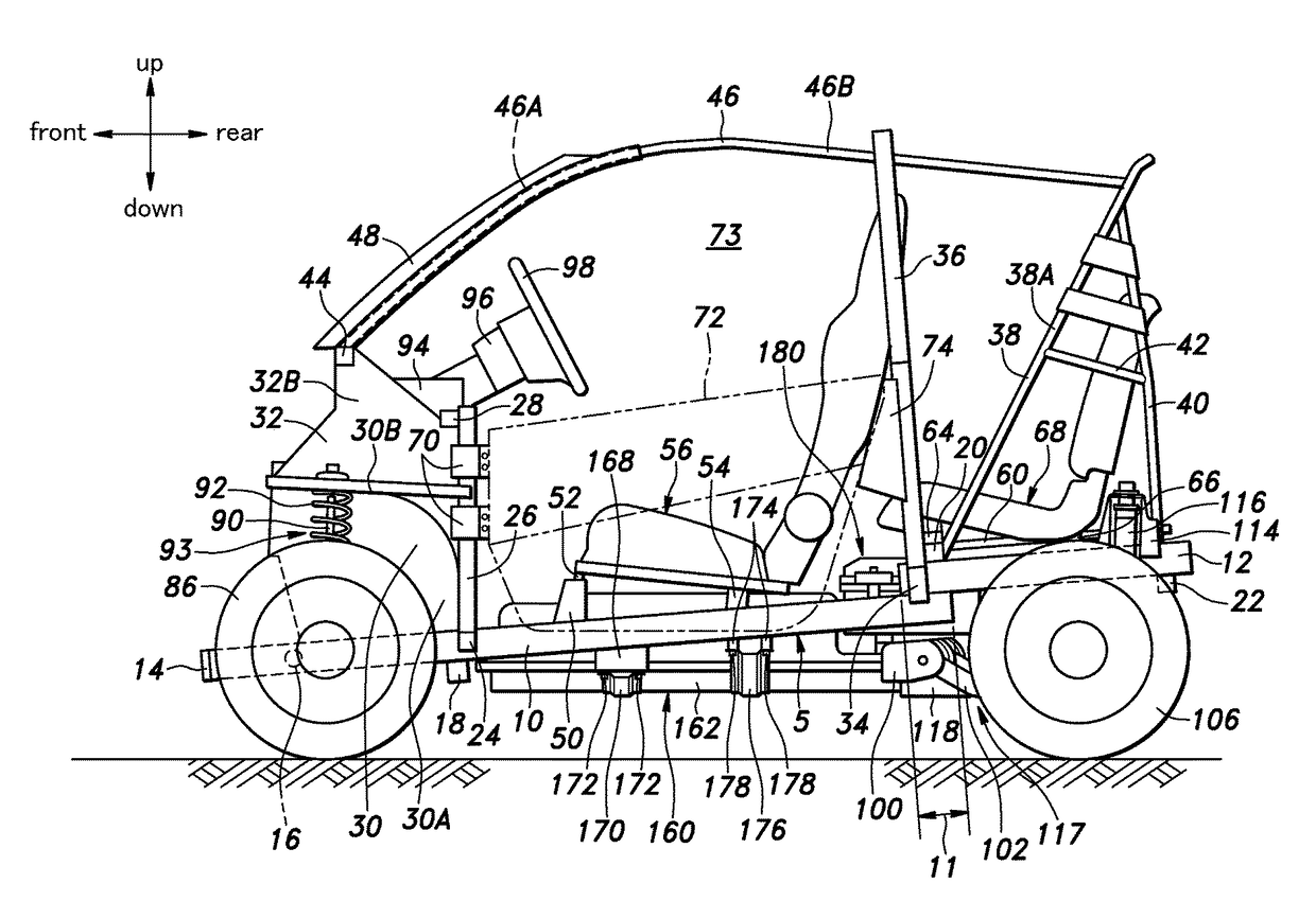
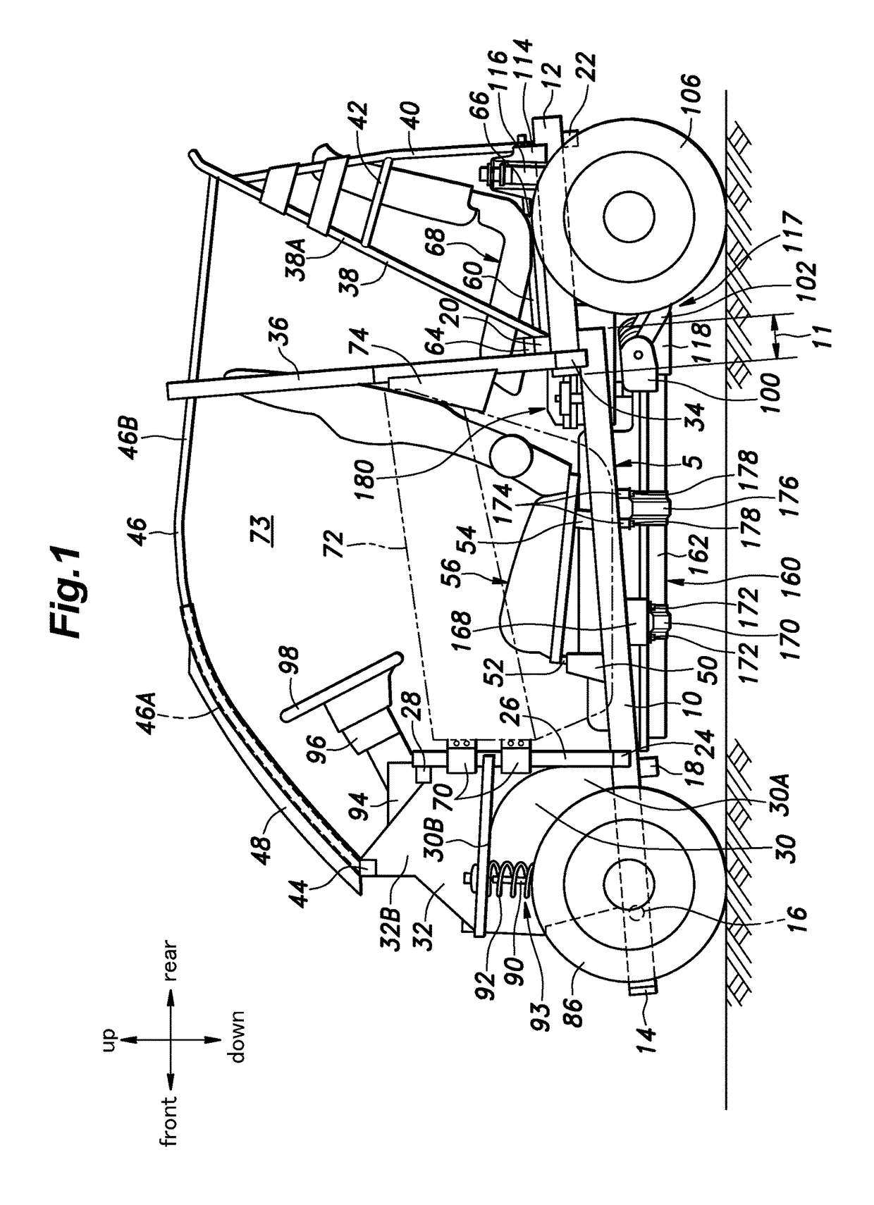
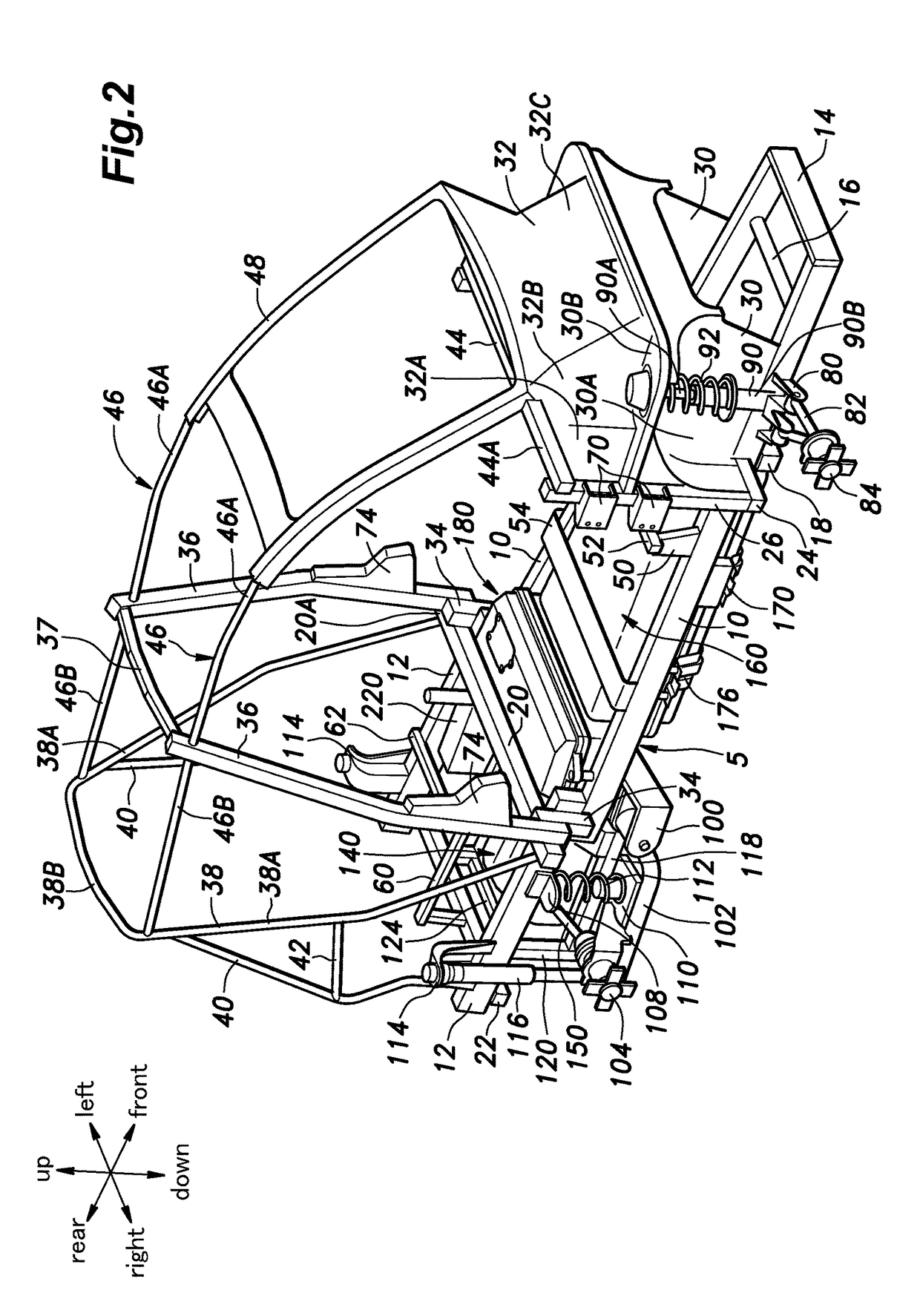
[0030]A four wheel vehicle embodying the present invention is described in the following with reference to FIGS. 1 to 9. In the following disclosure, various component parts are joined together by any per se known joining method such as welding, bonding and brazing among other possibilities.

(Lower Chassis Structure)

[0031]As shown in FIGS. 1 to 5, the four wheel vehicle of the illustrated embodiment includes a lower frame (lower chassis) 5 including a pair front side frames 10 and a pair of rear side frames 12 located on either side of the vehicle body. The front side frames 10 and the rear side frames 12 are each formed by an elongated straight steel member preferably made of a stamp formed member, a pipe member or any other member preferably having a closed cross section.

[0032]The front side frames 10 extend linearly at an angle relative to a horizontal plane, and with a progressively increasing spacing between the two front side frames 10 toward the rear ends thereof, and are dis...


PUM


Abstract

The four wheel vehicle uses an electric motor (142) for driving the vehicle and a battery unit (160) for supplying electric power to the electric motor. The lower chassis (5) of the vehicle includes a pair of front side frames (10) extending linearly in a fore and aft direction with an upward slant and a progressively increasing lateral mutual spacing from a front part thereof to a rear part thereof and a plurality of cross members (14, 16, 18) connecting the front side frames to each other. The battery unit is positioned between the two front side frames such that the battery unit overlaps with the front side frames in side view. Thereby, the battery unit can be effectively protected from side impacts.

Description

TECHNICAL FIELD[0001]The present invention relates to a four wheel vehicle, and in particular but not exclusively to a four wheel vehicle including an electric motor for propelling the vehicle and a battery unit for providing electric current to the electric motor.BACKGROUND ART[0002]An electrically powered four wheel vehicle typically includes a pair of side sill members extending horizontally in a fore and aft direction in a mutually parallel relationship, a pair of front side members connected to the front ends of the respective side sill members in a mutually parallel relationship, and a rear sub frame having a ladder or a cage structure connected to the rear ends of the side sill members. A pair of front wheels are supported by the front side members via respective strut suspension systems, and a pair of rear wheels are supported by the rear sub frame via respective strut or wishbone suspensions systems. A power unit including an electric motor is mounted on the rear sub frame....

Claims


Application Information

Patent Timeline
IPC IPC(8): B62D23/00B60N2/015B60N2/20B60G3/14B60G3/06B60G7/02B60G7/00B60G11/15B60G13/00B60G15/02B60L11/18B60R21/13B62D21/15B62D27/02B62D29/00B60L50/64
CPCB62D23/005B60G2300/50B60N2/015B60N2/20B60G3/14B60G3/06B60G7/02B60G7/008B60G11/15B60G13/005B60G13/003B60G15/02B60L11/1877B60L11/1818B60L11/1864B60R21/13B62D21/157B62D27/02B60Y2306/01B60L2210/10B60G2202/12B60G2202/10B60G2204/12422B60G2204/128B60G2204/129B62D29/007B60L50/50B60K1/04B60L3/00B62D21/00B60K2001/0422B60L50/64H01M50/249B62D21/02H01M10/625H01M10/6561B60L53/16B60L58/21B60L50/66Y02T10/70Y02T10/7072Y02T90/14Y02E60/10
Inventor KOBAYASHI, NAOKIIKUI, KUNIAKIKATO, TAKAHIRO
Owner HONDA MOTOR CO LTD
Why Eureka
Try Eureka