
Airfoil assembly with leading edge element

a technology of airfoil and leading edge element, which is applied in the direction of liquid fuel engine, machine/engine, efficient propulsion technology, etc., can solve the problems of high stress on the compressor, and the stress on the statator vanes and the rotating blades of the turbin

Active Publication Date: 2017-08-10
GENERAL ELECTRIC CO
View PDF12 Cites 28 Cited by
  • Summary
  • Abstract
  • Description
  • Claims
  • Application Information

AI Technical Summary

Benefits of technology

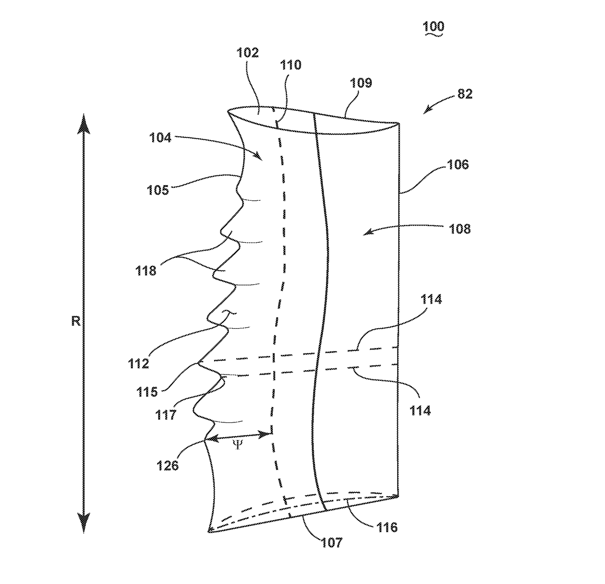
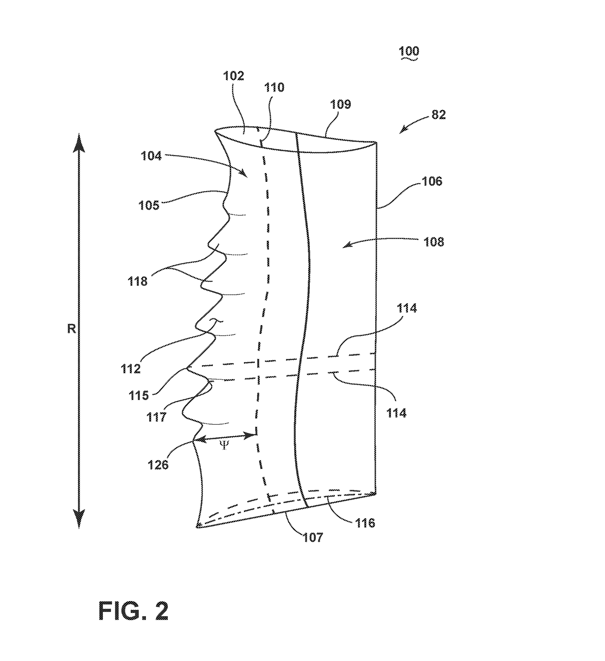
This patent describes an airfoil assembly with a leading edge element that has a 3-D shape with both chord and camber variations. The assembly also includes a trailing edge element and a connection to secure the leading edge element to the trailing edge element. The invention provides a method to form the airfoil by securing the leading edge element to the trailing edge element. The technical effect of this invention is to create an airfoil with improved aerodynamic performance and increased efficiency.

Problems solved by technology

Due to extreme temperatures of the combustion gas flow path and operating parameters, the stator vanes and rotating blades in both the turbine and compressor may become highly stressed with extreme mechanical and thermal loading.

Method used


Image

  • Airfoil assembly with leading edge element
  • Airfoil assembly with leading edge element
  • Airfoil assembly with leading edge element

Examples


Embodiment Construction

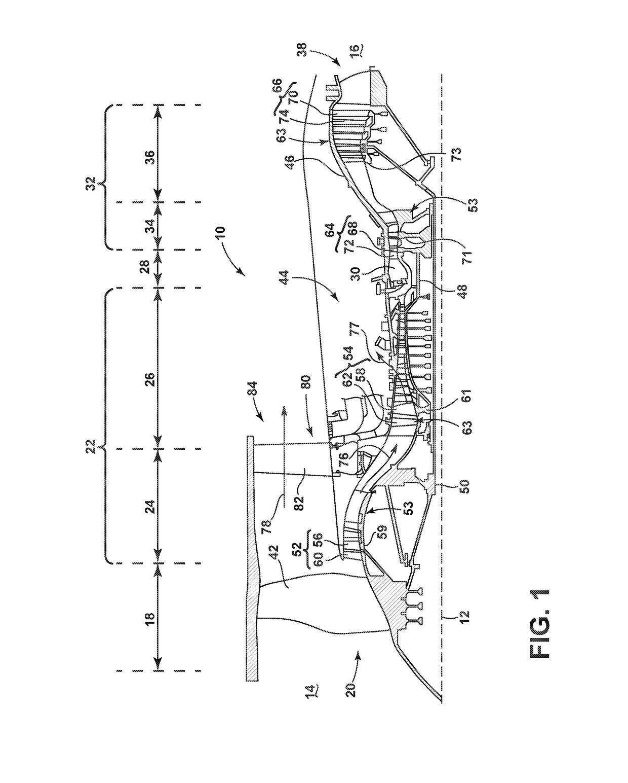
[0014]The described embodiments relate to an apparatus and method for fabricating an airfoil such as, but not limited to, for use in a rotary device. The embodiments described herein are not limiting, but rather are exemplary only. It should be understood that the disclosed embodiments may apply to any type of airfoil or aerodynamic surface, such as, but not limited to, fan blades, rotor blades, stator vanes, ducted fan blades, unducted fan blades, struts, vanes, nacelle inlets, open rotor propulsion systems, wind-turbine blades, propellers impellers, diffuser vanes, and / or return channel vanes. More specifically, the disclosed embodiments may apply to any airfoil, or aerodynamic surface.

[0015]The described embodiments of the present invention are directed to systems, methods, and other devices related to routing airflow in a turbine engine. For purposes of illustration, the present invention will be described with respect to an aircraft gas turbine engine. It will be understood, ho...


PUM


Abstract

An airfoil assembly including a composite body having a mounting edge and a trailing edge which is secured to a leading edge element defining a 3-D leading edge geometry with both chord and camber variation.

Description

BACKGROUND OF THE INVENTION[0001]Turbine engines, and particularly gas or combustion turbine engines, are rotary engines that extract energy from a flow of combusted gases passing through a fan with a plurality of blades, then into the engine through a series of compressor stages, which include pairs of rotating blades and stationary vanes, through a combustor, and then through a series of turbine stages, which include pairs of rotating blade and stationary vanes. In the compressor stages, the blades are supported by posts protruding from the rotor while the vanes are mounted to stator disks.[0002]During operation air is pressurized in the compressor and mixed with fuel in the combustor for generating hot combustion gases which flow downstream through the turbine stages. Due to extreme temperatures of the combustion gas flow path and operating parameters, the stator vanes and rotating blades in both the turbine and compressor may become highly stressed with extreme mechanical and th...

Claims


Application Information

Patent Timeline
Patent Type & Authority Applications(United States)
IPC IPC(8): F01D5/14F01D5/28F01D9/04
CPCF01D5/141F01D9/041F01D5/282F05D2250/29F05D2240/121F05D2300/603F05D2300/10F05D2220/323F02C6/20F01D5/288F05D2240/303F01D5/147F05D2250/184Y02T50/60F04D29/324
Inventor KRAY, NICHOLAS JOSEPHWOOD, TREVOR HOWARDSHIM, DONG-JINSHAH, PRANAV DHOJ
Owner GENERAL ELECTRIC CO
Learn More