Drive shaft and manufacturing method therefor

a technology of drive shaft and manufacturing method, which is applied in the field of drive shaft, can solve the problems of increasing weight, reducing the strength of cfrp material, and unable to obtain sufficient torsional strength and fatigue strength, so as to reduce the weight effectually, reduce the adhesive strength of adhesive, and avoid air like

Active Publication Date: 2017-08-10
HONDA MOTOR CO LTD
View PDF16 Cites 7 Cited by
  • Summary
  • Abstract
  • Description
  • Claims
  • Application Information

AI Technical Summary

Benefits of technology

[0027]More specifically, the shaft member and the tubular member can be serration-fitted together, and the fitting part can be arranged in the interior of the exterior sleeve. Further, the exterior sleeve and the tubular member can be firmly joined together through the film and the adhesive. As a result, since the shaft member and the tubular member can be joined together firmly, a drive shaft can be obtained, which has torsional strength and fatigue strength of a sufficient size or magnitude, and which is effectively reduced in weight.
[0028]In the above manufacturing method for the drive shaft, as the bonding assistance region, a suction pad structure preferably is disposed on the film. In this case, in the external fitting step, when the film and the adhesive are interposed between the exterior sleeve and the tubular member, the suction pad structure is crushed and a suction force is generated, and together therewith, the adhesive is made to flow and entrainment and the like of air can be avoided. Consequently, by both the suction force of the suction pad structure and the suitably filled adhesive, the exterior sleeve and the tubular member can be joined together more firmly. In addition, even if there is a decrease in the adhesive strength of the adhesive, by providing the bonding assistance region in the form of the suction pad structure, the joined condition between the exterior sleeve and the tubular member can be maintained, the thickness of the adhesive layer can easily be adjusted, and maintainability can be enhanced.
[0029]In the above manufacturing method for the drive shaft, plural bonding assistance regions preferably are arranged in alignment with respect to the film. In this case, since variations in the bonding strength at each of respective locations of the film can be suppressed, joining of the exterior sleeve and the tubular member can be performed more effectively.
[0030]In the above manufacturing method for the drive shaft, the bonding assistance region preferably is disposed on both surfaces of the film. In this case, the bonding strength of the bonding assistance region of the film is exerted effectively, and the exterior sleeve and the tubular member can be joined together more firmly.

Problems solved by technology

In this case, the strength of the CFRP material decreases, and hence, since the strength of the drive shaft as a whole decreases, there is a concern that sufficient torsional strength and fatigue strength cannot be obtained.
Further, an increase in weight cannot be avoided.
Furthermore, as in the joining method described in Japanese Laid-Open Patent Publication No. 05-215119, if joining is carried out using only an adhesive, it is likely for the bonding strength between the metallic material and the CFRP material to be insufficient.
Consequently, in such a method as well, it is difficult to obtain a drive shaft equipped with adequate torsional strength and fatigue strength.

Method used


Image

  • Drive shaft and manufacturing method therefor
  • Drive shaft and manufacturing method therefor
  • Drive shaft and manufacturing method therefor

Examples


Embodiment Construction

[0038]Concerning the drive shaft according to the present invention, a preferred embodiment in relation to a manufacturing method therefor will be described in detail below with reference to the accompanying drawings.

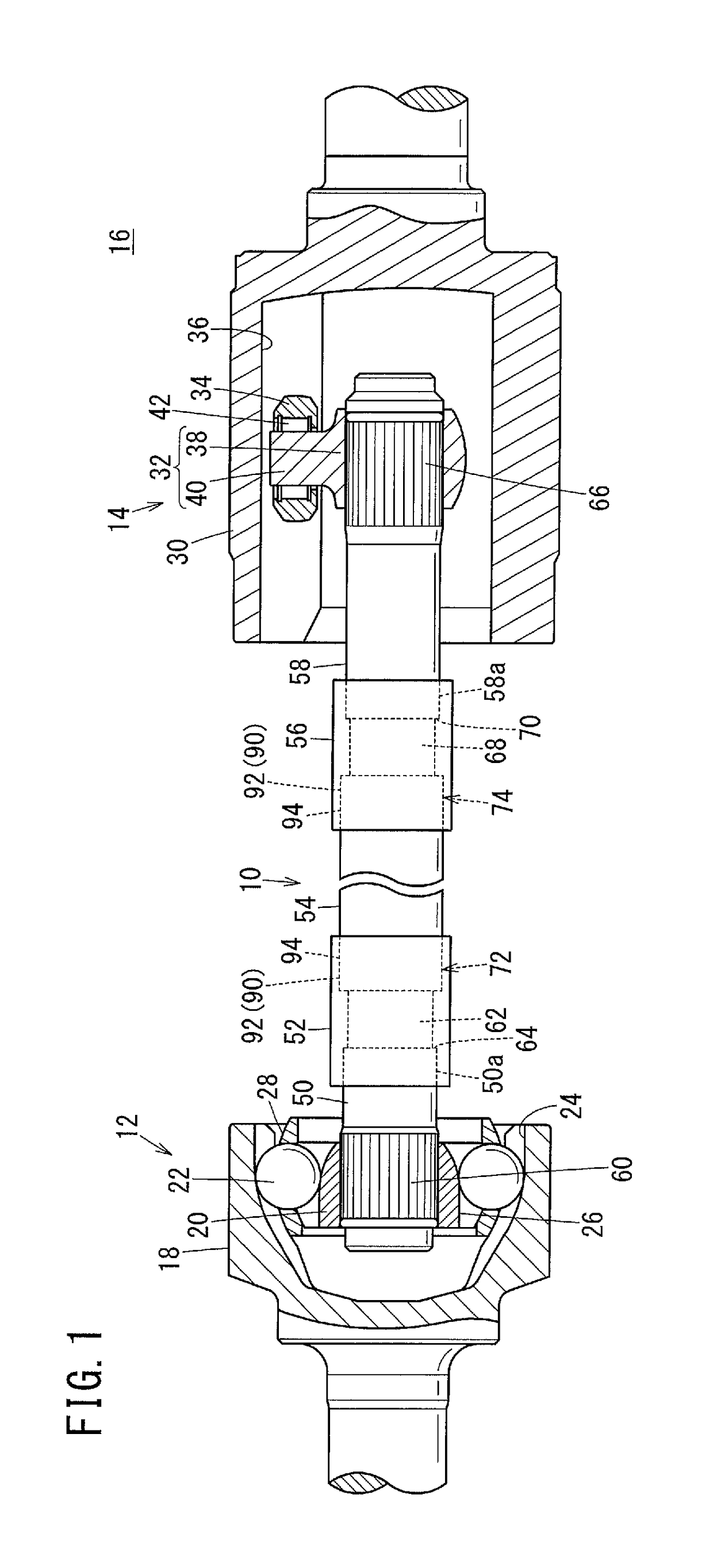
[0039]As shown in FIG. 1, a drive shaft 10 according to the present embodiment, together with a first constant velocity joint 12 and a second constant velocity joint 14, constitutes a power transmission device 16 of an automobile. First, the power transmission device 16 will be described.

[0040]The first constant velocity joint 12 is a Birfield type constant velocity joint on the outboard side, which is interposed between one end side (the left end side in FIG. 1) of the drive shaft 10 and a hub (not shown), and is constituted basically from an outer cup 18, an inner ring (race) 20, and balls 22. The outer cup 18 includes a cup-shaped part in which a bottomed hole is formed, and is connected integrally to the hub. On an inner surface of the outer cup 18 in the form of a ...


PUM

PropertyMeasurementUnit
Rockwell hardness HRCaaaaaaaaaa
outer diameteraaaaaaaaaa

Abstract

A drive shaft includes a first shaft member made of metal, a tubular member made of CFRP, and a first exterior sleeve. The first shaft member is capable of being attached on one end side thereof to a first constant velocity joint, and has a first serrated part on which serrations are formed on another end side thereof. The tubular member is formed with a first fitting part fitted externally over the first serrated part. The first exterior sleeve covers the first fitting part by being disposed to extend over outer circumferential surfaces of the first shaft member and the tubular member. A film provided with a bonding assistance region and an adhesive are interposed between the outer circumferential surface of the tubular member and the inner circumferential surface of the first exterior sleeve.

Description

CROSS-REFERENCE TO RELATED APPLICATION[0001]This application is based upon and claims the benefit of priority from Japanese Patent Application No. 2016-022417 filed on Feb. 9, 2016, the contents of which are incorporated herein by reference.BACKGROUND OF THE INVENTION[0002]Field of the Invention[0003]The present invention relates to a drive shaft and a manufacturing method therefor, in which the drive shaft is connected to and transmits torque between constant velocity joints.[0004]Description of the Related Art[0005]In automobiles that are driven electrically or by an engine, power (rotational torque) is transmitted to the drive wheels from the engine or a motor through a power transmission device disposed between the drive wheels and a reduction gear. The power transmission device, in general, is equipped with constant velocity joints (constant velocity universal joints) arranged at an interval at two locations in an axial direction, and a drive shaft connected to the constant vel...

Claims


Application Information

Patent Timeline
Patent Type & Authority Applications(United States)
IPC IPC(8): F16D3/06F16C3/02
CPCF16D3/06F16C3/02F16D2250/0069F16C2226/40B29L2031/75B29C66/721B29C66/74283B29C65/48B29C66/5221F16C2208/02F16B11/008F16C3/023B29C65/5007B29C65/5057B29C65/76B29C66/1222B29C66/1224B29C66/52292B29C66/5344B29C66/7212B29C66/742B29C66/8262F16D1/027F16D1/068F16D3/2055F16D3/223F16D2003/22323F16C3/026F16C2326/06F16D1/072B29K2307/04F16B4/004B23P19/02
Inventor KAMIKAWA, MITSURU
Owner HONDA MOTOR CO LTD
Why Eureka
Try Eureka