
Spill resistant battery cover and vent cover

Inactive Publication Date: 2017-08-10
CPS TECH HLDG LLC
View PDF6 Cites 1 Cited by
  • Summary
  • Abstract
  • Description
  • Claims
  • Application Information

AI Technical Summary

Benefits of technology

The solution effectively vents gases, prevents electrolyte leakage, and allows for electrolyte replenishment, while being cost-effective and roll-over compliant, ensuring safe operation and maintenance of lead acid batteries.

Problems solved by technology

Additionally, in various exemplary lead acid or other flooded batteries, the aqueous electrolyte may periodically need to be replenished as the electrolyte and / or water is lost to the above-outlined gassing effect.

Method used


Image

  • Spill resistant battery cover and vent cover
  • Spill resistant battery cover and vent cover
  • Spill resistant battery cover and vent cover

Examples


Embodiment Construction

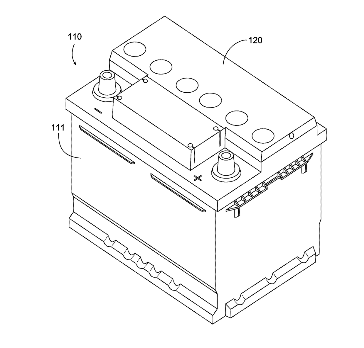
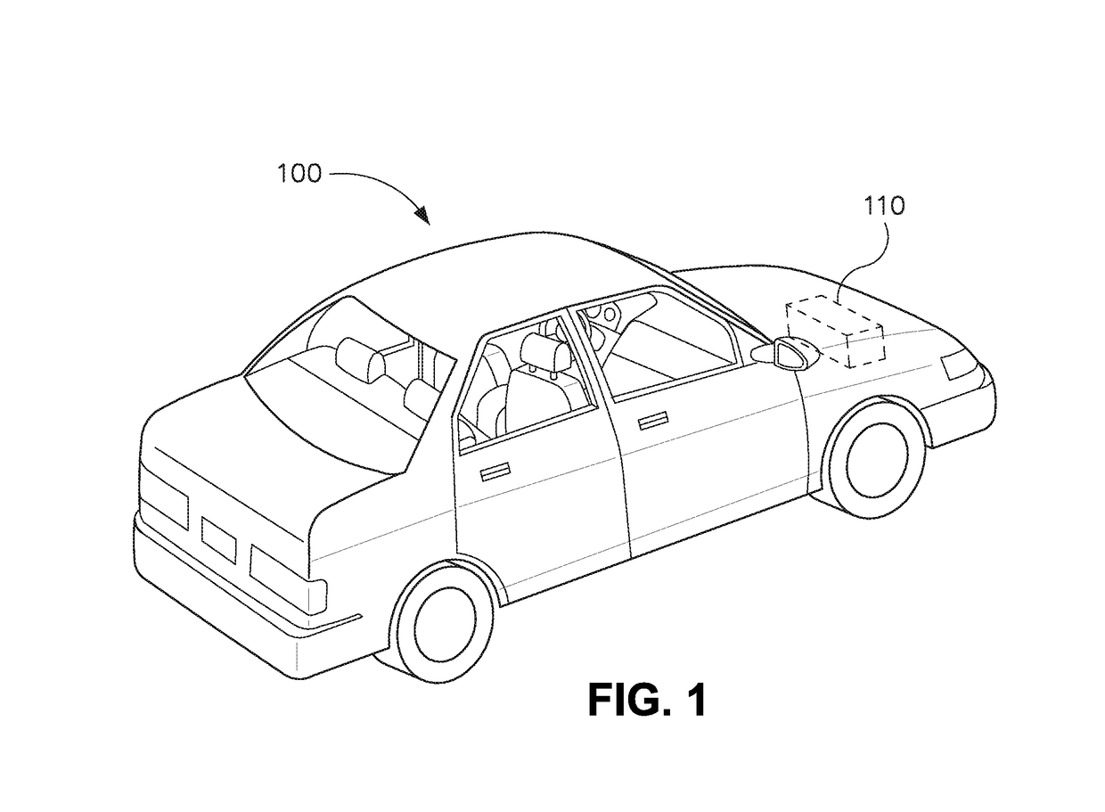
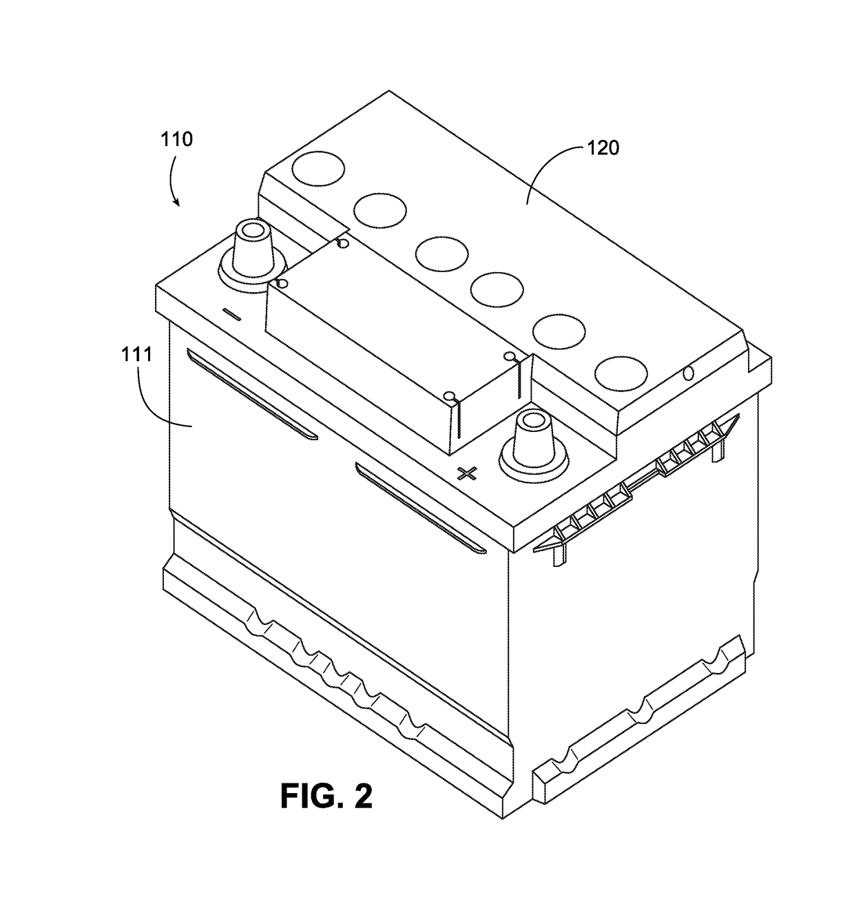
[0044]Referring to FIG. 1, a vehicle 100 is shown according to an exemplary embodiment that includes a battery 110. While the vehicle is shown as an automobile, according to various alternative embodiments, the vehicle may comprise a wide variety of differing types of vehicles including, among others, motorcycles, buses, recreational vehicles, boats, and the like. According to an exemplary embodiment, the vehicle uses an internal combustion engine for locomotive purposes. The battery is configured to provide at least a portion of the power required to start or operate the vehicle and / or various vehicle systems (e.g., lighting and ignition systems). It should be understood that, while the battery shown in FIG. 1 is located near the front of the vehicle under a hood of the vehicle, in various other exemplary embodiments, the battery may be located in other positions. For example, in various exemplary embodiments the battery is located in a trunk of the vehicle or in a passenger compar...


PUM


Abstract

A vented battery cover with a vent cover is disclosed. The vent cover may be capable of attachment to the battery at a first position and a second position using one or more first snap features and one or more second snap features. The vent cover may also provide a fluid path from a fill tube hole in the battery cover to a vent wherein the path is a labyrinth.

Description

PRIORITY[0001]This application is a divisional of U.S. Non-Provisional patent application Ser. No. 13 / 144,414 filed Nov. 4, 2011, which claims priority to U.S. Provisional Application No. 61 / 144,277 filed Jan. 13, 2009, and which is a national stage entry of International Application No. PCT / US2010 / 20951 both of which are incorporated herein by reference in their entirety.BACKGROUND[0002]1. Field of the Invention[0003]The present invention relates to a spill-resistant battery cover and manifold or vent cover.[0004]2. Related Art[0005]Exemplary lead acid or other flooded batteries may include a number of lead or lead alloy plates submersed in an aqueous electrolyte (e.g., aqueous sulfuric acid). During a charging and / or a discharging stage of using an exemplary lead acid or other flooded battery, gases may be produced and, in exemplary unsealed lead acid batteries, these gases may need to be vented to an external environment to prevent dangerous conditions (e.g., explosive build up o...

Claims


Application Information

Patent Timeline
Patent Type & Authority Applications(United States)
IPC IPC(8): H01M2/12H01M10/06H01M50/147H01M50/367
CPCH01M2/1217H01M2220/20H01M10/06H01M2/1252H01M50/3425H01M50/367H01M50/147Y02E60/10H01M10/16H01M50/308
Inventor ANDERSEN, GLENN W.
Owner CPS TECH HLDG LLC
Features
  • Generate Ideas
  • Intellectual Property
  • Life Sciences
  • Materials
  • Tech Scout
  • Unparalleled Data Quality
  • Higher Quality Content
  • 60% Fewer Hallucinations
Learn More