Wire connection terminal structure

a wire connection and terminal technology, applied in the direction of connections, electrical equipment, connection contact material, etc., can solve the problems of complex structure of the conductive frame b>7/b>, unoptimized design form, large area of entirely stretched raw materials, etc., to improve the support strength of the entire wire connection terminal structure, prevent deformation, and improve the wire connection terminal structure

Active Publication Date: 2017-08-10
SWITCHLAB +1
View PDF0 Cites 11 Cited by
  • Summary
  • Abstract
  • Description
  • Claims
  • Application Information

AI Technical Summary

Benefits of technology

[0008]It is therefore a primary object of the present invention to provide an improved wire connection terminal structure. The wire connection terminal structure includes a leaf spring, a conductive plate and a fixing frame, which are mounted in an insulation case and assembled with each other to form a wire connection terminal. The support strength of the entire wire connection terminal structure is enhanced so that the wire connection terminal structure is prevented from deforming due to external force. Moreover, the structures of the respective components of the wire connection terminal are simplified to lower the manufacturing cost. The present invention overcomes the shortcoming of the conventional wire connection terminal that the conductive frame has insufficient support strength so that the cantilever and the base section are easy to deform to reduce the utility. The present invention also overcomes the shortcoming of the conventional wire connection terminal that in the manufacturing process of the conductive frame and the leaf spring, a great amount of wasted material is produced so that the material cost is wasted. The present invention further overcomes the shortcoming of the conventional wire connection terminal that the conductive frame and the leaf spring have complicated structures and are uneasy to process.

Problems solved by technology

As a result, the structure of the conductive frame 7 is complicated.
This is not an optimal design form.
Also, the area of the entirely stretched raw material is quite large.
As a result, a great amount of wasted material is produced in the manufacturing process.
Therefore, much material cost is wasted.

Method used


Image

  • Wire connection terminal structure
  • Wire connection terminal structure
  • Wire connection terminal structure

Examples


Embodiment Construction

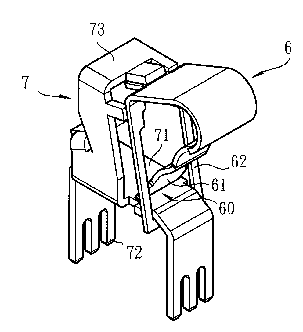
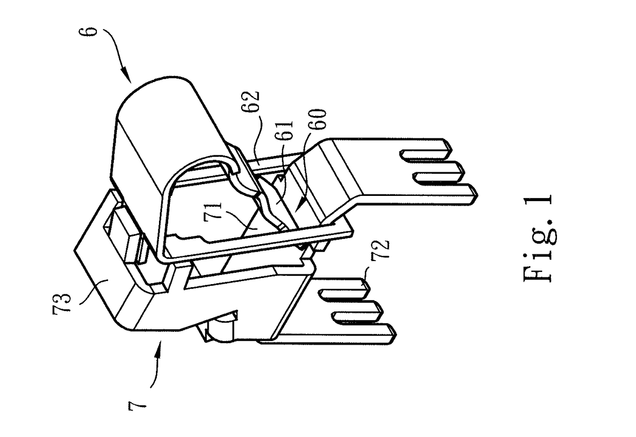
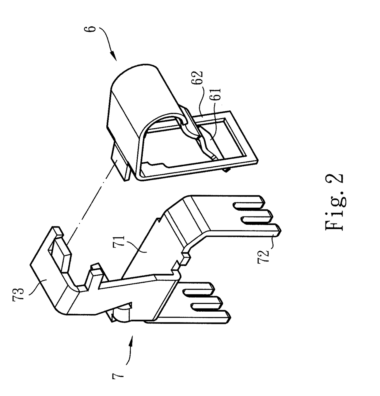
[0026]Please refer to FIGS. 3 and 5. According to a preferred embodiment, the wire connection terminal structure of the present invention includes a leaf spring 1, a conductive plate 2 and a fixing frame 3, which are mounted in an insulation case 4. The leaf spring 1 and the conductive plate 2 are framed and connected with the fixing frame 3. The conductive plate 2 is formed with abase section 21 assembled on the fixing frame 3 and at least one soldering leg 22 extending from the base section 21 out of the case 4. The leaf spring 1 is formed with an elastic swingable holding section 11 extending to a position in contact with the base section 21. The holding section 11 and the base section 21 define therebetween an elastic holding mouth 10. Preferably, the conductive plate 2 is made of a high-conductivity material (such as copper), which has an electrical conductivity better than the leaf spring 1 and the fixing frame 3. The leaf spring 1 is made of a material (such as elastic steel)...


PUM


Abstract

A wire connection terminal structure includes a leaf spring, a conductive plate and a fixing frame framing and connecting with the leaf spring and the conductive plate. The conductive plate is formed with a base section assembled with the fixing frame. The leaf spring is formed with an elastic swingable holding section extending to a position in contact with the base section. The holding section and the base section define therebetween an elastic holding mouth. An external electrical wire can be plugged into the holding mouth and held between the holding section and the base section and electrically connected with the conductive plate. The conductive plate and the fixing frame are two separate components so that the conductive plate is solely made of a high-conductivity material, while the fixing frame is made of a material with higher structural rigidity.

Description

BACKGROUND OF THE INVENTION[0001]1. Field of the Invention[0002]The present invention relates generally to a wire connection terminal structure, and more particularly to an improved wire connection terminal structure for an external electrical wire to plug in and electrically connect therewith. The structure of the conductive plate of the wire connection terminal is simplified and the assembling strength of the entire wire connection terminal is enhanced. Therefore, the manufacturing cost of the wire connection terminal is lowered.[0003]2. Description of the Related Art[0004]A wire connection terminal is also referred to as an electrical connector. The wire connection terminal is mainly used to electrically connect the electrical wires between electronic components, electrical apparatuses, electronic equipments and circuit boards. In practice, the electronic components generally include resistors, capacitors, inductors, LED, transformers, liquid crystal panels, touch panels, etc. Th...

Claims


Application Information

Patent Timeline
Patent Type & Authority Applications(United States)
IPC IPC(8): H01R4/48H01R4/58H01R9/24H01R12/51
CPCH01R4/4818H01R9/2408H01R4/58H01R12/515H01R12/707H01R4/48275H01R4/48185
Inventor WU, CHIH-YUANCHEN, WEI-CHICHEN, JHENG-WEI
Owner SWITCHLAB
Why Eureka
Try Eureka