Optical signal comprising a succession of multi-band bursts of multi-carrier data signals, system and method of emission of such a signal, and corresponding optical transport network

a multi-carrier data signal and optical signal technology, applied in the field of optical communication networks, can solve the problems of obs technique not benefiting from the possibility of optical memories, the filling of transmission channels can be relatively inefficient, and the traffic is increasingly burst with a “packet” nature, so as to achieve low phase noise and low phase noise. , the effect of increasing the degree of freedom

Active Publication Date: 2017-08-10
ORANGE SA (FR)
View PDF8 Cites 10 Cited by
  • Summary
  • Abstract
  • Description
  • Claims
  • Application Information

AI Technical Summary

Benefits of technology

[0049]Indeed, the use of external cavity lasers having very low phase noise is particularly suited to the technology of OFDM multi-carrier modulation which is highly sensitive to phase noise prompting interference between sub-carriers (ICI or inter-carrier interference). In addition, the use of such lasers pre-set on certain wavelengths and associated with optical switches having low response times (for example semi-conductor amplifiers used as optical gates) constitutes an interesting alternative to rapidly tunable lasers with very low phase noise. The advances being made in optical integration should furthermore make it possible, in the near future, to make this assembly on a single component.
[0050]According to one particular aspect of this embodiment, said external cavity lasers are common to at least two of said source nodes thus advantageously making it possible to pool the sources on the sending side.
[0051]According to another embodiment of the invention, said spectral band associated with one of said source nodes is variable so as to offer an additional degree of freedom in the flexibility offered to adapt the granularity of the bandwidth used to the quantity of data to be transported. In this case, the control plane must also make it possible to control the allocation of the spectral bands to the different source nodes.

Problems solved by technology

The downside of this increase in the bit rate of interfaces is that the filling of the transmission channels can be relatively inefficient if it is not done by electronic aggregation that is costly in terms of optical-electrical-optical (O-E-O) conversion interfaces and uneconomical in terms of energy.
This solution was especially impelled by the increase in traffic volumes and the generalization of IP traffic, resulting in an increasingly bursty traffic with a “packet” nature.
However, contrary to electronic switching, the OBS technique does not benefit from the possibility of having optical memories and circumvents this problem either by using methods of burst contention management or by very precisely controlling the sending periods at the sources.
This second solution however is limited by the fact that with the bit rate increasing, the bandwidth of the channels possesses a minimum value that is non-compressible.
This has a negative impact on the services offered and especially the real time-services.
This can still be far too high to carry out an efficient filling of this band.
While this solution is interesting in that it proposes the simultaneous use of the spectral and time domains to adapt the allocated bandwidth according to the bandwidth required for data transmission, it has little flexibility in the management of the resource.
In addition, it relies on a fast switch-based routing technique which is not economical in energy.

Method used


Image

  • Optical signal comprising a succession of multi-band bursts of multi-carrier data signals, system and method of emission of such a signal, and corresponding optical transport network
  • Optical signal comprising a succession of multi-band bursts of multi-carrier data signals, system and method of emission of such a signal, and corresponding optical transport network
  • Optical signal comprising a succession of multi-band bursts of multi-carrier data signals, system and method of emission of such a signal, and corresponding optical transport network

Examples


Embodiment Construction

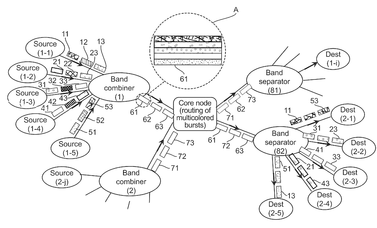
[0089]The general principle of the invention relies on the combination of two time and spectral solutions for accessing the sub-wavelength granularity in an optical transmission network, that makes it possible to scale up the capacity of the networks by offering the finest possible granularity, while at the same time enabling an increase in the bit rate per channel up to one terabit / s (or even beyond) and offers increased flexibility as compared with prior-art techniques.

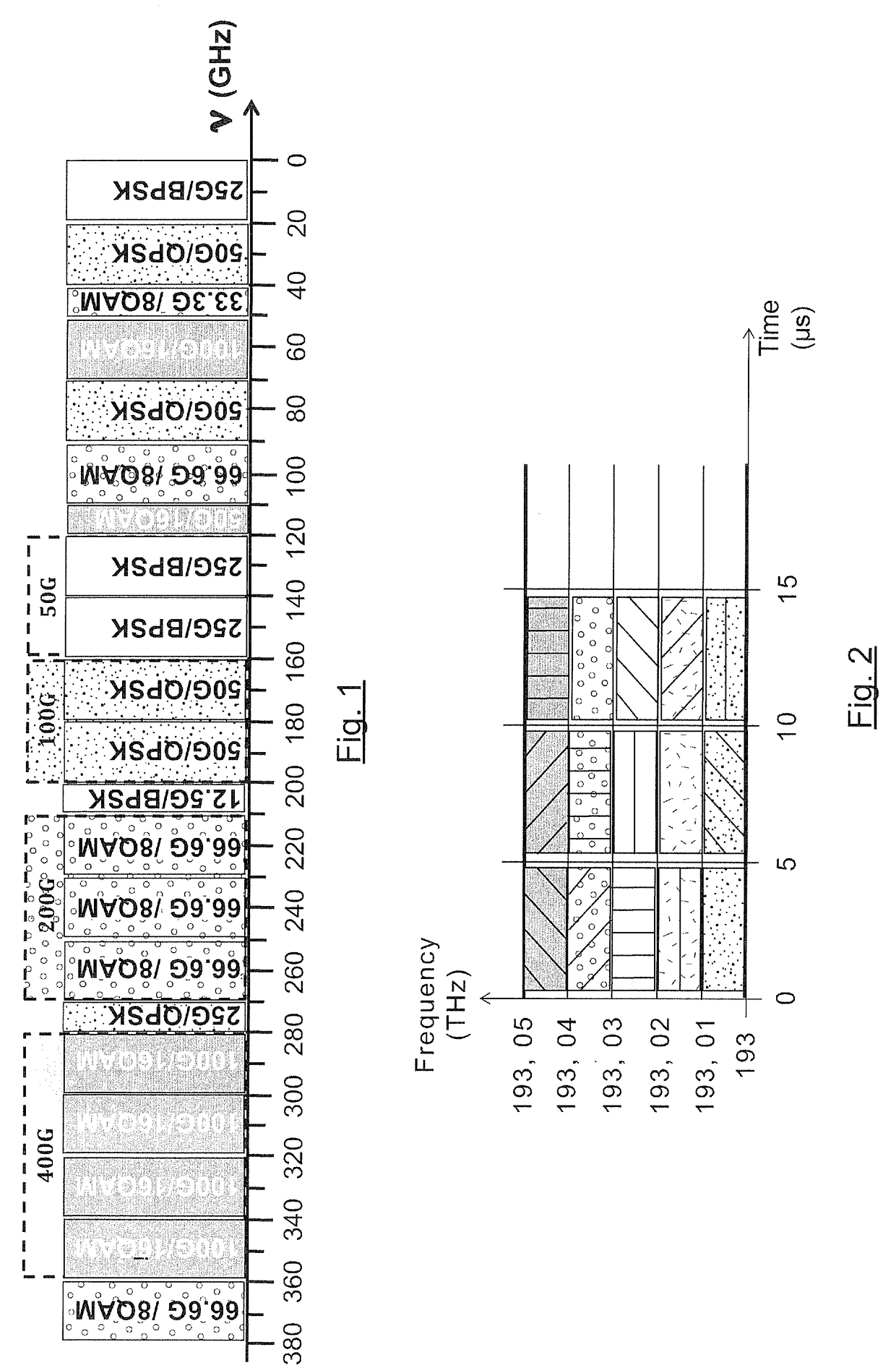
[0090]Referring to FIG. 2, we now present an example of a representation of a transmission channel sub-divided according to the general principle of the invention explained above, namely:[0091]time sub-division by data bursts (in FIG. 2, the data bursts have a duration of 4.5 μs for a slot duration of 5 μs for example) and[0092]a spectral sub-division by bands (10 GHz, five bands being illustrated in FIG. 2 to form a 50 GHz channel).

[0093]In FIG. 2, each of the background patterns (shaded, with small circles, dots, ...


PUM


Abstract

The invention relates to a system for sending data in an optical network comprising source nodes (1-1, 1-2, 1-3, 1-4, 1-5), each capable of generating, in a spectral band that is associated with it, a multi-carrier optical data signal obtained by modulation of a source signal at a source wavelength and of sending this signal in the form of single-band data bursts (11-13, 21-23, 31-33, 41-43, 51-53) that can be associated with distinct source wavelengths, and a combiner (1,2) for combining single-band data bursts, sent by the source nodes in the spectral bands that are associated with them, into multi-band data bursts (61-63, 71-73) occupying a spectral band corresponding to a juxtaposition of the spectral bands associated with the source nodes. In this system, a unit for controlling an instant of sending of said single-band data bursts by the source nodes, implements a control plane taking account of a path time of the single-band data bursts sent by the source nodes to the combiner.

Description

1. FIELD OF THE INVENTION[0001]The field of the invention is that of optical communications networks. More specifically, the invention relates to the improvement of the use of network resources in such optical networks.2. PRIOR ART AND ITS DRAWBACKS[0002]The exponential growth of the volume of data exchanged within optical communications networks is dictating a constant increase in the bit rates of transmission interfaces, now reaching 100 Gbit / s and more.[0003]The downside of this increase in the bit rate of interfaces is that the filling of the transmission channels can be relatively inefficient if it is not done by electronic aggregation that is costly in terms of optical-electrical-optical (O-E-O) conversion interfaces and uneconomical in terms of energy.[0004]However, there are two optical solutions that can be used to access the sub-wavelength granularity and thus lead to a better use of resources by filling the transmission channels more efficiently. The first solution uses t...

Claims


Application Information

Patent Timeline
Patent Type & Authority Applications(United States)
IPC IPC(8): H04J14/02H04L27/26H04L27/00H04Q11/00
CPCH04J14/0241H04Q11/0066H04L27/2627H04Q2011/0016H04Q11/0005H04Q2011/0086H04Q2011/0018H04L27/0008H04B10/506H04B10/548H04J14/0298
Inventor GAVIGNET, PAULETTEPINCEMIN, ERWANLE ROUZIC, ESTHER
Owner ORANGE SA (FR)
Why Eureka
Try Eureka