
Supervised 4-d dose map deformation for adaptive radiotherapy planning

a dose map and adaptive radiotherapy technology, applied in radiation therapy, x-ray/gamma-ray/particle irradiation therapy, radiation therapy, etc., can solve the problem that the human professional cannot know when and/or under what conditions a treatment plan should be re-optimized, and the standard implementation of imrt does not take into account the eventuality of the anatomy of the treated site change, etc. problems, to achieve the effect of ensuring the safety of patients, ensuring the stability

Active Publication Date: 2017-08-17
KONINKLIJKE PHILIPS ELECTRONICS NV
View PDF2 Cites 9 Cited by
  • Summary
  • Abstract
  • Description
  • Claims
  • Application Information

AI Technical Summary

Benefits of technology

The present invention provides a method and apparatus for decision-making in radiation treatment plan adaptation. The method involves establishing a spatial registration transformation between a previous image and a current image of a target site, computing the magnitude of the transformation, and applying the transformation to an existing dose distribution map for the target site to obtain a deformed dose map. The method also includes computing a photon fluence vector based on the deformed dose map, indicating the deformation of the target site. The deformation can be evaluated based on a pre-defined criterion, and if the deformation does not meet the criterion, the dose distribution map can be re-computed. The computed deformation magnitude can be used as a reference for the accuracy of the dose map. The invention provides a faster and more efficient way to adapt the radiation treatment plan.

Problems solved by technology

Standard IMRT implementations do not take into account the eventuality that the anatomy of the treated site may change throughout the course of radiation delivery.
But still, in existing schemes, no clues are provided to the human professional on when and / or under what conditions a treatment plan should be re-optimized.
The information available to medical personal to reach such a decision may be overwhelming and it may be difficult to draw definite conclusion on how to proceed.
This problem is further compounded by the limited resources available to national health services as plan adaptions may prove expensive.

Method used


Image

  • Supervised 4-d dose map deformation for adaptive radiotherapy planning
  • Supervised 4-d dose map deformation for adaptive radiotherapy planning
  • Supervised 4-d dose map deformation for adaptive radiotherapy planning

Examples


Embodiment Construction

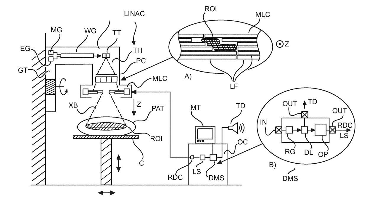
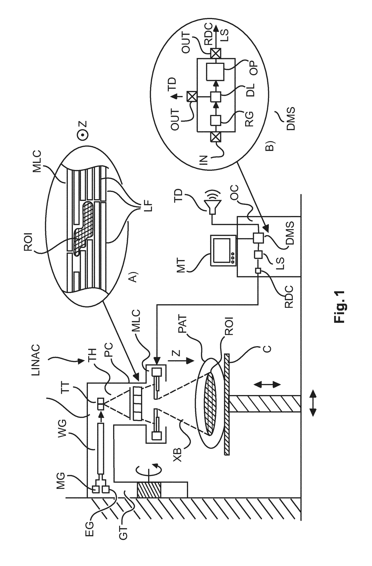
[0029]With reference to FIG. 1, there is shown an arrangement for delivering radiation in radiation therapy. The main goal in radiation therapy is to kill off cancerous tissue ROI in an animal or human patient PAT. More particularly the objective is to kill off as much of the cancerous tissue as possible but at the same time to spare as much of the healthy tissue as possible that surrounds the cancerous tissue.

[0030]A high energy x-ray treatment beam XB is radiated across the cancerous tissue ROI, preferably from a number of different angles.

[0031]Radiation therapy is achieved by using a linear accelerator system (referred to herein as “LINAC”). The LINAC system is to be used for IMRT. The LINAC comprises a rotatable gantry GT. The gantry is rotatable around a treatment region and around one or more axis. Only one rotation axis is shown in FIG. 1 (see the rounded arrow) but this for illustrative purposes only and in no way limiting as the LINAC may include more than one axis of rota...


PUM


Abstract

Method and apparatus (DMS) for dosage management in radiation therapy planning and / or delivery. Images of a region of interest ROI are acquired at different times. A registration transformation is computed that deforms one of the two images into the other. A magnitude of the transformation is then computed based on a suitable metric. If the computed magnitude is found to comply with a pre-defined criterion, the transformation is used to deform a dose distribution map and compute, based on the deformed dose map, therefrom a new fluence map.

Description

FIELD OF THE INVENTION[0001]The invention relates to a method for dose management in respect of a region of interest, to a dose management apparatus, to a computer program product, and to a computer readable medium.BACKGROUND OF THE INVENTION[0002]Cancer remains one of the scourges of mankind and radiation therapy is one of the chief tools to combat same. In radiation therapy a high energy treatment radiation beam is used to destroy cancerous tissue whilst sparing healthy one.[0003]A particular type of radiation therapy planning called Intensity Modulated Radiotherapy (IMRT) allows spatially modulating a treatment beam to precisely conform not only in shape but also in terms of prescribed dosage requirements as per a treatment plan.[0004]Standard IMRT implementations do not take into account the eventuality that the anatomy of the treated site may change throughout the course of radiation delivery.[0005]Although in the past some more advanced schemes have been proposed on how to ada...

Claims


Application Information

Patent Timeline
Patent Type & Authority Applications(United States)
IPC IPC(8): A61N5/10
CPCA61N5/1031A61N2005/1089A61N5/1045A61N5/1037
Inventor ISOLA, ALFONSO AGATINOFONTANAROSA, DAVIDE
Owner KONINKLIJKE PHILIPS ELECTRONICS NV
Learn More