Condition monitoring system and wind power generation system comprising the same

a technology of condition monitoring and wind power generation, which is applied in the direction of gas-turbine engine testing, mechanical equipment, machines/engines, etc., can solve the problem of not being easy to replace with another

Inactive Publication Date: 2017-08-17
NTN CORP
View PDF7 Cites 11 Cited by
  • Summary
  • Abstract
  • Description
  • Claims
  • Application Information

AI Technical Summary

Benefits of technology

[0027]According to the present invention, a failure of a yaw bearing which supports a nacelle on top of a tower turnably can early be detected.

Problems solved by technology

The yaw bearing is provided at a high place and generally has a large size, and accordingly it is not easy to replace it with another.

Method used


Image

  • Condition monitoring system and wind power generation system comprising the same
  • Condition monitoring system and wind power generation system comprising the same
  • Condition monitoring system and wind power generation system comprising the same

Examples


first embodiment

[0039]

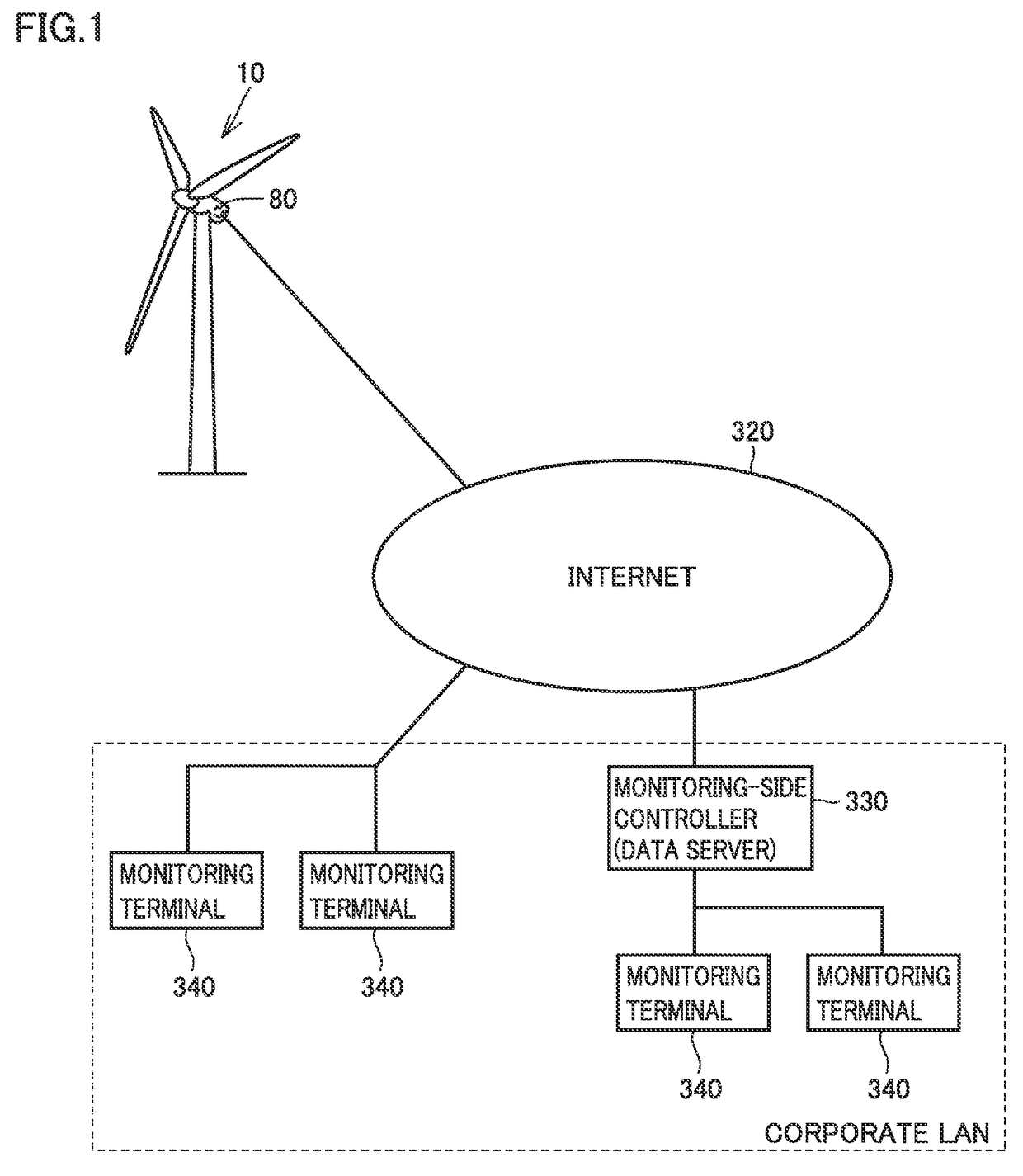
[0040]FIG. 1 schematically shows a general configuration of a condition monitoring system according to a first embodiment. With reference to FIG. 1, the condition monitoring system includes a monitor device 80, a data server (a monitoring-side controller) 330, and a monitoring terminal 340.

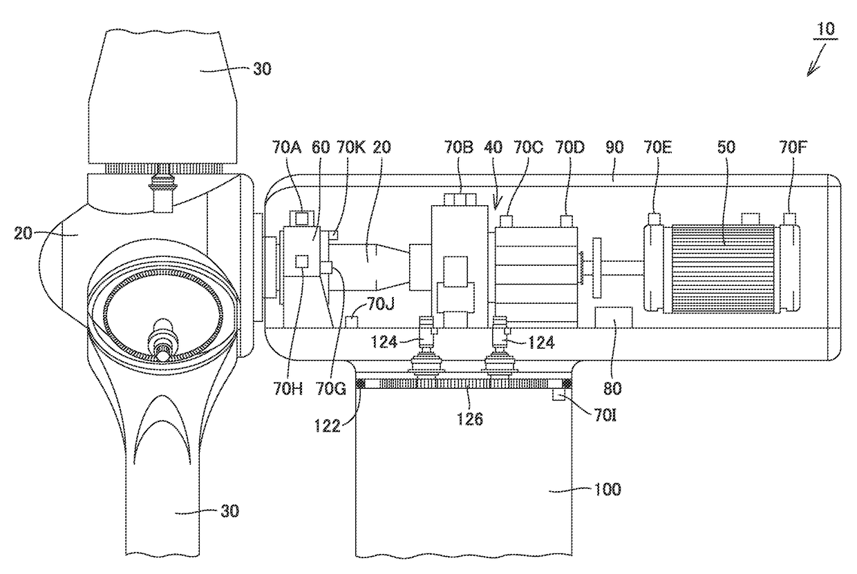
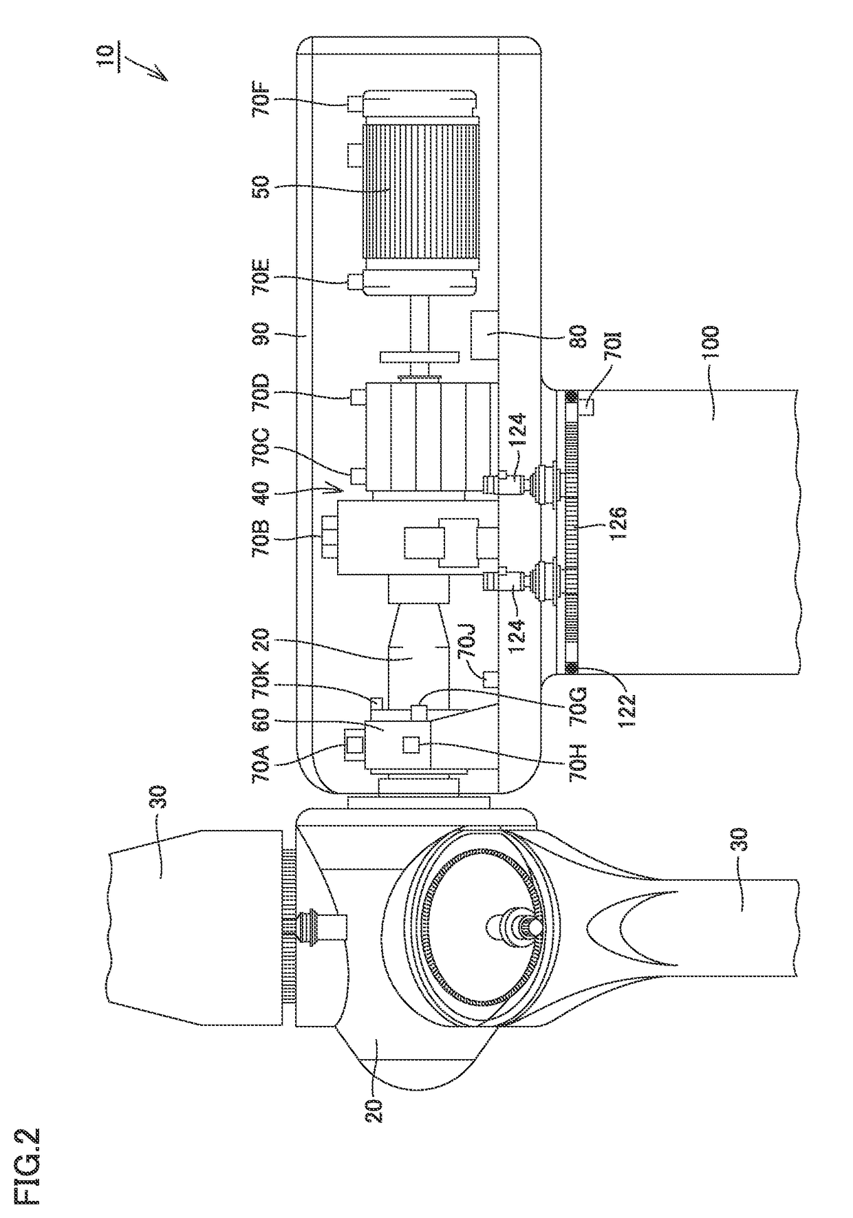
[0041]Monitor device 80 calculates an effective value, a peak value, a crest factor, an effective value after an envelope process, a peak value after the envelope process, etc. from values sensed by sensors 70A-70I (see FIG. 2) described later, and transmits them to data server 330 via Internet 320. Furthermore, monitor device 80 transmits a measured value of a rotating angular velocity of the main shaft of wind turbine 10 and that of a rotating angular velocity of the nacelle thereof to data server 330 via Internet 320. Monitor device 80 and data server 330 may communicate via a wire or may communicate wirelessly.

[0042]Data server 330 and monitoring terminal 340 are connected via a corporat...

second embodiment

[0106]In the above first embodiment, main shaft 20 having rotating angular velocity ωm within a prescribed range (including main shaft 20 being stopped) is defined as a yaw bearing diagnosing, operating condition, and accordingly, when a wind condition (or a wind speed) changes frequently, a diagnosis parameter may insufficiently be collected.

[0107]Accordingly, in this second embodiment, a diagnosis parameter collected without imposing a condition on the rotating angular velocity of main shaft 20 is corrected depending on rotating angular velocity ωm of main shaft 20, and a failure of yaw bearing 122 is diagnosed based on the diagnosis parameter an effect of rotation of main shaft 20 on which is suppressed.

[0108]The second embodiment provides a condition monitoring system having a general configuration, wind turbine 10 having a configuration, and a diagnosis parameter and a failure mode having a relationship, which are identical to those of the first embodiment.

[0109]And in the cond...

third embodiment

[0134]While in the second embodiment, a diagnosis parameter of yaw bearing 122 is corrected depending on rotating angular velocity ωm of main shaft 20, the diagnosis parameter may be corrected depending on an amount of electric power generated by power generator 50, rather than rotating angular velocity ωm of main shaft 20. In other words, variation in amount of electric power generated is ganged with that of transmission torque acting on speed up gear 40, and also manifests as variation of vibration in a vicinity of yaw bearing 122. Accordingly, in a third embodiment, a diagnosis parameter of yaw bearing 122 is corrected depending on an amount of electric power generated by power generator 50.

[0135]Correcting the diagnosis parameter depending on the amount of electric power generated by power generator 50 can be done in a methodology similar to that of the second embodiment. In other words, from an average value of the amount of electric power generated by power generator 50 and a ...


PUM


Abstract

A condition monitoring system for a wind turbine comprises: a sensor which senses a condition of a yaw bearing; a monitor device which generates a diagnosis parameter based on a detection result of the sensor; a sensor which senses a rotating angular velocity of a nacelle and that of a main shaft; and a data server which diagnoses a failure of the yaw bearing based on the diagnosis parameter. The data server diagnoses whether the yaw bearing has a failure, based on a variation of the diagnosis parameter from an initial value thereof when the nacelle has a rotating angular velocity within a non-zero, first prescribed range and the main shaft has a rotating angular velocity within a second prescribed range.

Description

TECHNICAL FIELD[0001]The present invention relates to a condition monitoring system and a wind power generation system comprising the same, and particularly to a condition monitoring system provided for a wind turbine comprising a yaw bearing which supports a nacelle on top of a tower turnably and a wind power generation system comprising the same.BACKGROUND ART[0002]Japanese Patent Laying-Open No. 2013-185507 (patent document 1) discloses a condition monitoring system (CMS) which monitors a condition of a mechanical element of a wind turbine. This condition monitoring system takes in a signal of a vibration sensor provided to the mechanical element, records over a long period of time how a quantity of a condition representing a state of vibration in a rated operation (hereafter referred to as a diagnosis parameter) varies with time, and based on the diagnosis parameter's increase rate, a feature of the variation and the like, determines whether the mechanical element has a failure ...

Claims


Application Information

Patent Timeline
Patent Type & Authority Applications(United States)
IPC IPC(8): F03D17/00F03D9/25G01M15/14F03D7/04
CPCF03D17/00F03D7/042F05D2260/80G01M15/14F03D9/25F03D7/0204F05B2240/50F03D80/70Y02E10/72
Inventor SAKAGUCHI, TOMOYA
Owner NTN CORP
Why Eureka
Try Eureka