Baseboard luminaire for ambient lighting

a technology for luminaires and baseboards, applied in the field of lighting elements, can solve problems such as creating sufficient distance between light sources

Active Publication Date: 2017-08-17
SIGNIFY HLDG BV
View PDF4 Cites 13 Cited by
  • Summary
  • Abstract
  • Description
  • Claims
  • Application Information

AI Technical Summary

Benefits of technology

[0004]From interior lighting design it is concluded that there is a wish to create an impressive lighting effect with minimally visible elements, preferable unobtrusively

Problems solved by technology

A drawback of illuminating large areas of the ceiling or wall is that one has to

Method used


Image

  • Baseboard luminaire for ambient lighting
  • Baseboard luminaire for ambient lighting
  • Baseboard luminaire for ambient lighting

Examples


Embodiment Construction

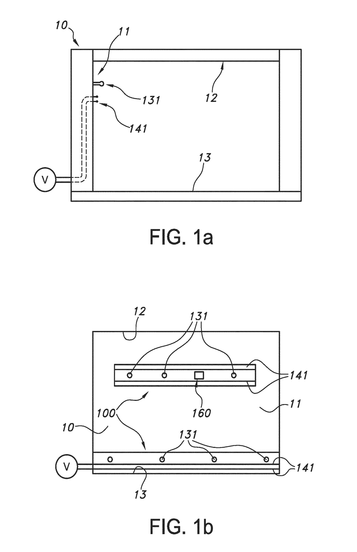
[0047]FIG. 1a schematically depicts (in side view) a building part 10, here a wall 11, comprising a first attachment unit 131 and a first electrical power connector 141. The power lines are drawn with dashes, to indicate that these lines may be within the building part. Reference 12 indicates a ceiling and reference 13 indicates a floor.

[0048]FIG. 1b schematically depicts such first attachment unit 131 and electrical power connector 141 integrated in a (elongated) building element 100. Such building element may be attached to a wall or ceiling, in principle anywhere. Here, two options are indicated, with the lower e.g. suitable to arrange a lighting element in the form of a flour molding, and with the higher one e.g. suitable to attach as strip like lighting element. Reference 160 indicates a building element control unit. Note that the electrical connectors are provided as line connectors, providing a lot of freedom where to arrange a lighting element. Of course, the electrical con...


PUM


Abstract

The invention provides an elongated lighting element (200) for attachment to a building part (10) selected from the group consisting of a wall (11), a ceiling (12) and a floor (13), wherein the building part (10) comprises a first attachment unit (131) and a first electrical power connector (141), wherein the elongated lighting element has a front side (210) and at the other side of the front side (210) (i) a second attachment unit (231) for forming with the first attachment unit (131) said attachment to said building part (10), (ii) a second electrical power connector (241) for forming an electrical connection with the first electrical power connector (141), and (iii) a plurality of solid state based light sources (250) configured to provide light source light (251) and functionally connected with the second electrical power connector (241).

Description

FIELD OF THE INVENTION[0001]The invention relates to a lighting element, especially for e.g. wall washing applications. The invention also relates to a lighting system comprising such lighting element, as well as to a method for providing such lighting element or lighting system to a building part.BACKGROUND OF THE INVENTION[0002]The use of wall washing lighting is known in the art. U.S. Pat. No. 4,748,543, for instance, describes a fluorescent indirect lighting fixture having its light source concealed from normal view by locating the lamps in a partially wrapped-around region to one side of an offset reflector, which is shaped in a special concave curvature to produce uniform “wall wash” illumination. A producible high quality reflective surface with required curvature maintained by a rigid accurate reflector assembly is achieved by utilizing a thin flexible reflective lining of high purity aluminum conformally laminated against a rigid extruded aluminum reflector body of required...

Claims


Application Information

Patent Timeline
IPC IPC(8): F21V33/00E04F19/04F21S4/28G08B7/06F21V21/02F21S8/00
CPCF21V33/006F21V21/02F21S8/033F21S4/28E04F2019/0454E04F19/0436F21Y2103/10F21Y2115/10G08B7/066F21V21/088F21W2111/027
Inventor KRIJN, MARCELLINUS PETRUS CAROLUS MICHAELGOMMANS, HENDRIKUS HUBERTUS PETRUSGHELUWE, JOCHEN RENAAT
Owner SIGNIFY HLDG BV
Why Eureka
Try Eureka