Pet detector scintillator arrangement with light sharing and depth of interaction estimation

a scintillator and detector technology, applied in the field of nuclear medicine medical imaging, can solve the problems of affecting system throughput, difficult, if not impossible, side measurement, etc., and achieve the effects of simple computation of doi, excellent timing resolution, and excellent spatial resolution

Active Publication Date: 2017-08-17
KONINKLJIJKE PHILIPS NV +1
View PDF6 Cites 7 Cited by
  • Summary
  • Abstract
  • Description
  • Claims
  • Application Information

AI Technical Summary

Benefits of technology

[0006]Another approach uses larger crystal arrays, such as 14×14 with light sharing surfaces between adjacent crystals, and to side calibrate the crystal array in a continuous DOI measurement. However, the larger arrays with broader light sharing impact timing resolution. Timing resolution is based on the sensed light output peak in a full width at half maximum (FWHM) measure used to determine a time of detection. As the light sharing increases, the peak broadens and the timing resolution broadens, i.e. decreases precision of the detected time. Moreover, the continuous DOI with the side measurement involves a more complex computation which affects system throughput, and the side measurement is difficult, if not impossible, in a ring of detectors disposed side by side.
[0012]Another advantage resides in the detector crystal arrangement with excellent timing resolution.

Problems solved by technology

However, the larger arrays with broader light sharing impact timing resolution.
Moreover, the continuous DOI with the side measurement involves a more complex computation which affects system throughput, and the side measurement is difficult, if not impossible, in a ring of detectors disposed side by side.

Method used


Image

  • Pet detector scintillator arrangement with light sharing and depth of interaction estimation
  • Pet detector scintillator arrangement with light sharing and depth of interaction estimation
  • Pet detector scintillator arrangement with light sharing and depth of interaction estimation

Examples


Embodiment Construction

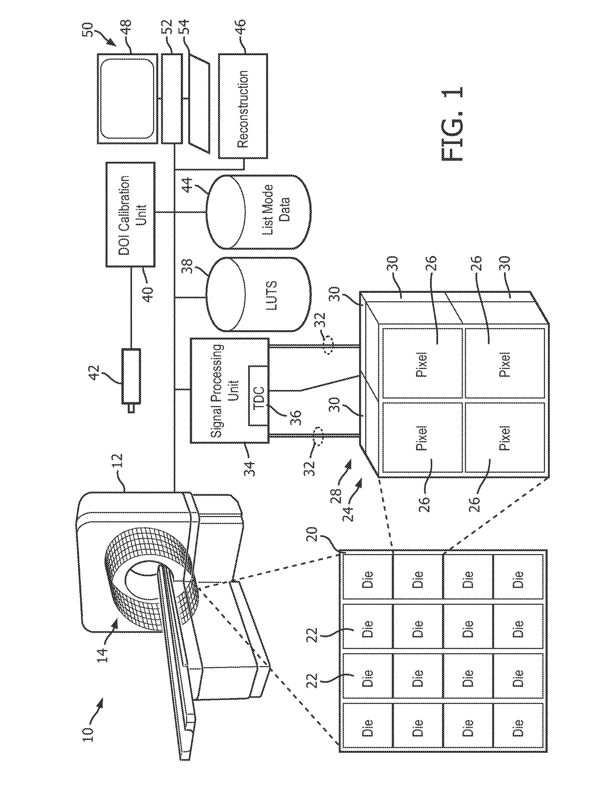
[0027]With reference to FIG. 1, an embodiment of a photon detector scintillator arrangement with light sharing and depth of interaction estimation system 10 is diagrammatically illustrated. The system 10 includes a positron emission tomography scanner or imaging device 12, which includes one or more detector rings 14 circumscribing an imaging region 16 shown in perspective with the detector rings 14 exposed. The imaging region 16 receives a subject supported on a subject support 18 and the subject, injected with a radiopharmaceutical, emits gamma photons received by the detector rings 14.

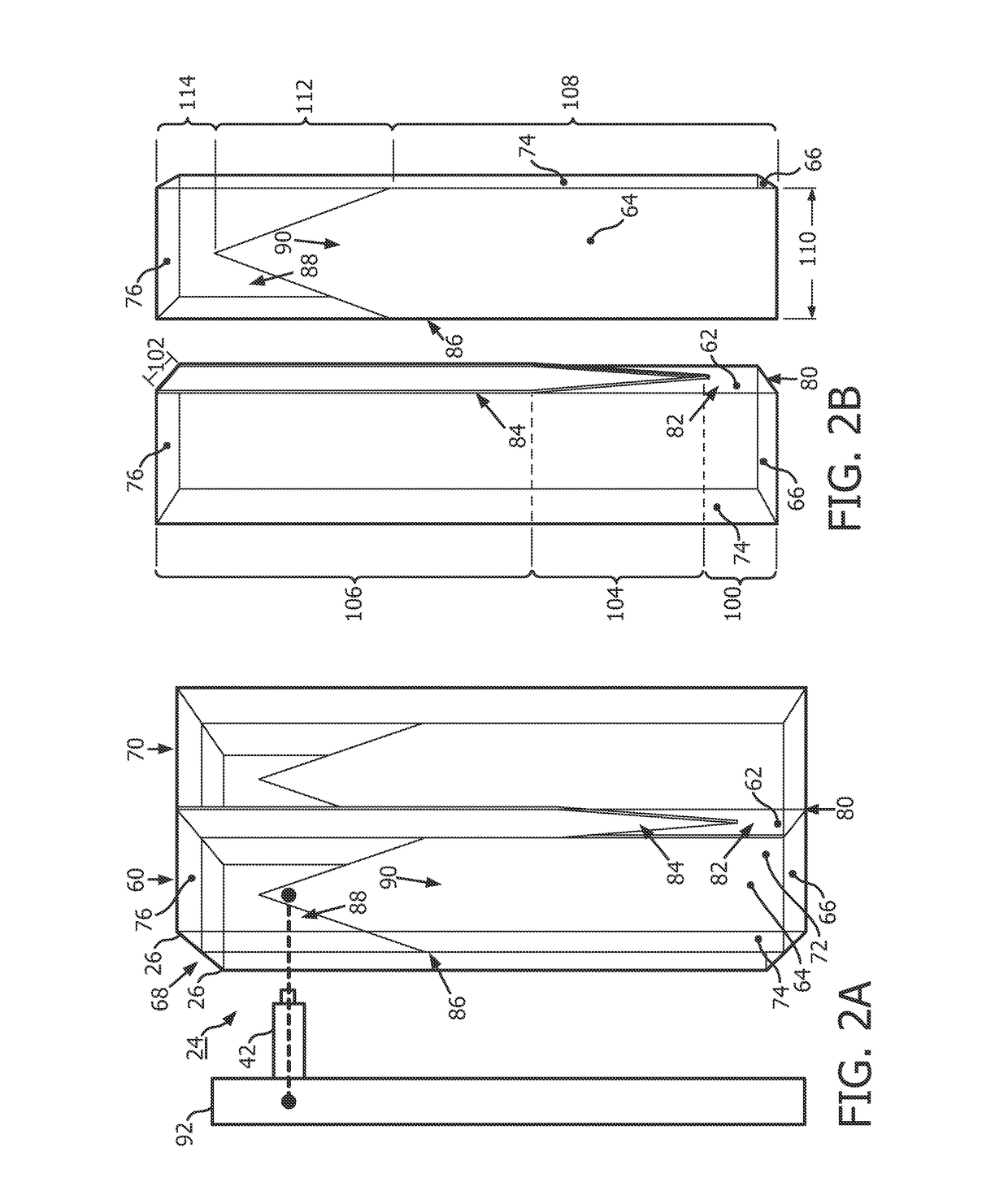
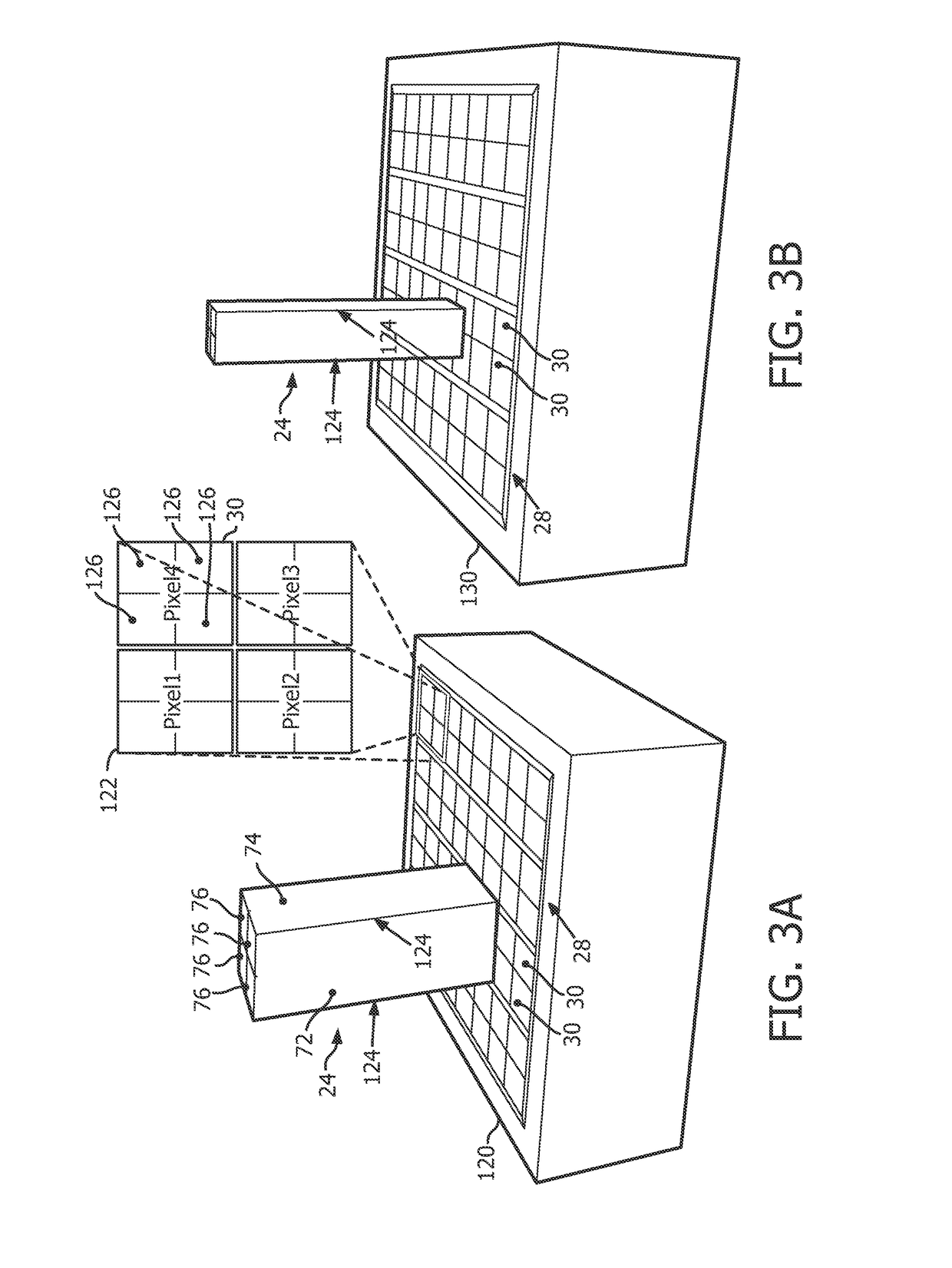
[0028]Each detector ring 14 includes detector tiles 20 arranged circumferentially around the imaging region 16. Each detector tile 20 includes a two-dimensional arrangement of dies 22 shown in an exploded center facing view. Each die 22 includes a scintillator array 24 of four substantially identical scintillator crystal bars 26, such as LYSO (lutetium-yttrium oxy-orthosilicate), Lutetium Oxy-Orthos...


PUM


Abstract

A photon detector includes a sensor array of optical sensors disposed in a plane and four substantially identical scintillation crystal bars. Each optical sensor is configured to sense luminescence. Each of the four scintillator crystal bars being a rectangular prism with four side surfaces and first and second end surfaces, each scintillation bar has two side surfaces which each face a side surface of another scintillation bar, and each scintillation crystal bar generating a light scintillation in response to interacting with a received gamma photon. A first layer (80) is disposed in a first plane disposed between and adjacent facing side surfaces of the four substantially identical scintillation crystal bars with a light sharing portion (82) adjacent the first end surface and a reflective portion (84) adjacent the second end surface. A second layer (68) is disposed in a second plane orthogonal to the first plane and disposed between and adjacent facing side surfaces of the four substantially identical scintillation crystal bars with a light sharing portion (88) adjacent the second end surface and a reflective portion (90) adjacent the first end surface.

Description

BACKGROUND[0001]The following relates generally to nuclear medicine medical imaging. It finds particular application in conjunction with Positron Emission Tomographic (PET) detectors and localization of positron annihilation events, and will be described with particular reference thereto. However, it will be understood that it also finds application in other usage scenarios and is not necessarily limited to the aforementioned application.[0002]In PET imaging, a subject is injected with a radiopharmaceutical targeting metabolic processes. The radiopharmaceutical accumulates in the targeted tissues and emits positrons as the radiopharmaceutical decays. The positron interacts with an electron in an annihilation event, which generates two gamma photons of 511 keV energy directed 180° opposite to each other. During the period of pharmaceutical decay, the subject is placed in an imaging device or scanner, which includes detectors that detect the generated gamma photons. The imaging device...

Claims


Application Information

Patent Timeline
Patent Type & Authority Applications(United States)
IPC IPC(8): G01T1/164G01T1/202G01T1/20
CPCG01T1/1644G01T1/202G01T1/2018G01T1/20182G01T1/20183G01T1/20
Inventor SOWARDS-EMMERD, DAVIDLEHNERT, ADRIENNEHUNTER, WILLIAMMIYAOKA, ROBERTSHAO, LINGXIONGLAURENCE, THOMAS LEROY
Owner KONINKLJIJKE PHILIPS NV
Why Eureka
Try Eureka