Method of Aberration Correction and Charged Particle Beam System
- Summary
- Abstract
- Description
- Claims
- Application Information
AI Technical Summary
Benefits of technology
Problems solved by technology
Method used
Image

Examples
first embodiment
1. First Embodiment
1.1. Transmission Electron Microscope
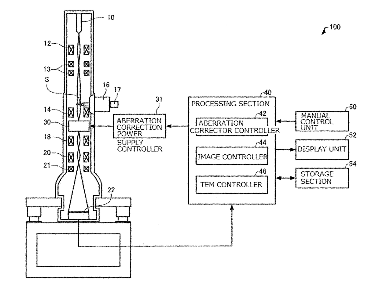
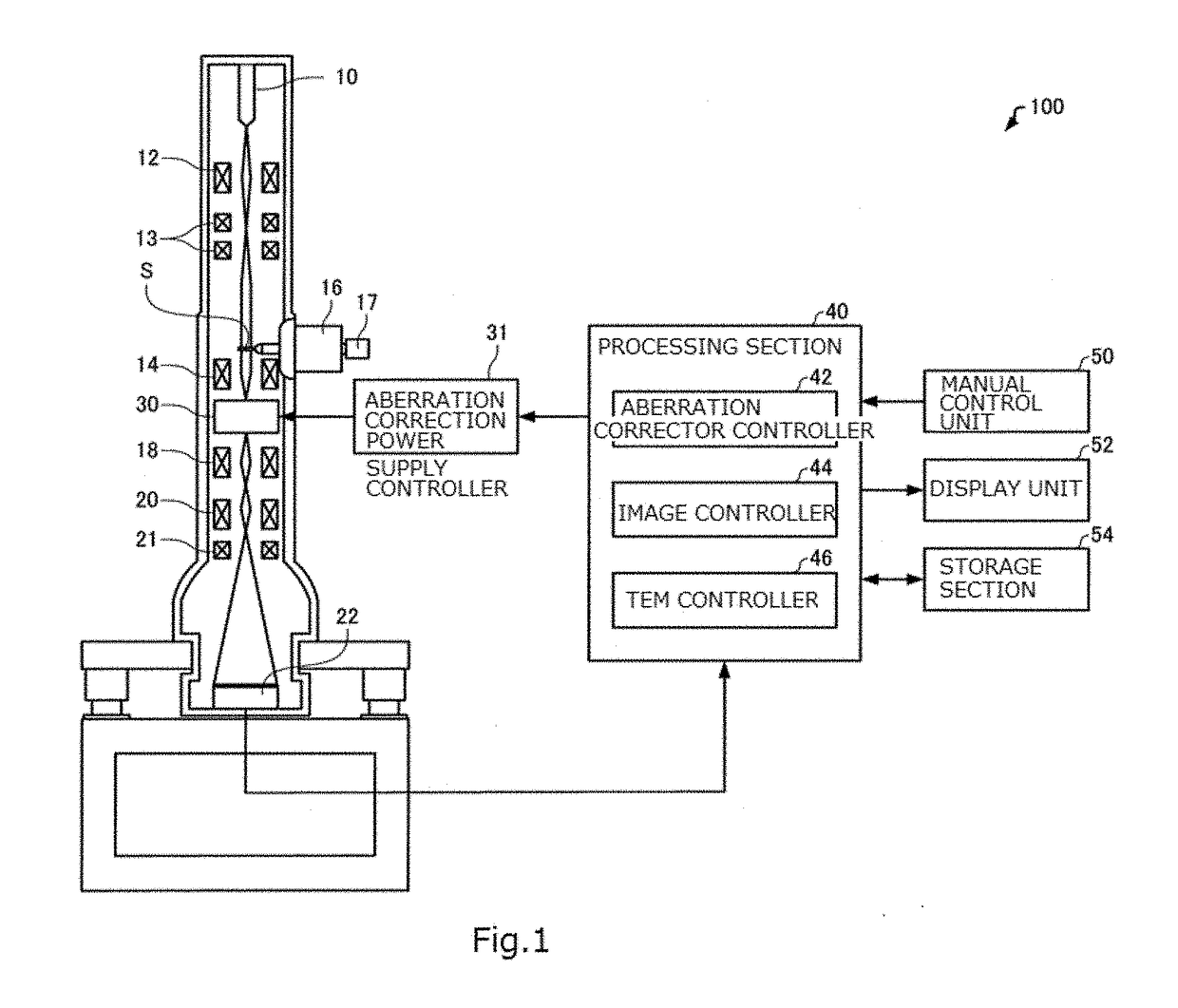
[0053]A transmission electron microscope (which is one example of charged particle beam system) associated with a first embodiment of the present invention is first described by referring to FIG. 1, which schematically shows the transmission electron microscope, 100, associated with the first embodiment.
[0054]As shown in FIG. 1, the transmission electron microscope 100 includes an electron source 10, a condenser lens system 12, alignment coils 13, an objective lens 14, a sample stage 16, a sample holder 17, an intermediate lens 18, a projector lens 20, deflection coils 21, an imager 22, a processing section 40, a manual control unit 50, a display unit 52, and a data storage section 54.
[0055]The electron source 10 produces electrons. For example, the electron source 10 is an electron gun which emits an electron beam by accelerating electrons, emitted from a cathode, by means of an anode.
[0056]The condenser lens system 12 focuses...
second embodiment
2. Second Embodiment
2.1. Transmission Electron Microscope
[0131]A transmission electron microscope associated with a second embodiment of the present invention is next described by referring to FIGS. 12 and 13. FIG. 12 schematically shows the transmission electron microscope, generally indicated by reference numeral 200, associated with the second embodiment. FIG. 13 schematically shows an aberration corrector 230 of the transmission electron microscope 200.
[0132]Those members of the transmission electron microscope 200 associated with the second embodiment which are similar in function to their respective counterparts of the transmission electron microscope 100 associated with the first embodiment are hereinafter indicated by the same reference numerals as in the above referenced figures and a detailed description thereof is omitted.
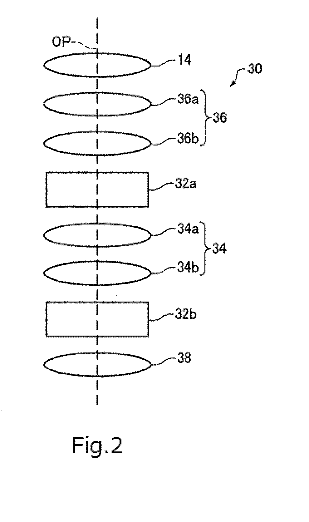
[0133]In the above-described transmission electron microscope 100, as shown in FIG. 2, the aberration corrector 30 has two stages of multipole elements ...
third embodiment
3. Third Embodiment
3.1. Electron Microscope
[0158]A transmission electron microscope associated with a third embodiment is next described by referring to FIG. 20, which schematically shows the transmission electron microscope, generally indicated by reference numeral 300, associated with the third embodiment.
[0159]Those members of the transmission electron microscope 300 associated with the third embodiment which are similar in function to their respective counterparts of the transmission electron microscope 100 associated with the first embodiment are hereinafter indicated by the same reference numerals as in the above referenced figures and a detailed description thereof is omitted.
[0160]As shown in FIG. 20, the transmission electron microscope 300 is different from the transmission electron microscope 100 in that the processing section 40 includes a first measuring portion 48a, a second measuring portion 48b, a first transfer lens system controller 49a, a second transfer lens syst...
PUM
 Abstract
Description
Claims
Application Information
 - Generate Ideas
- Intellectual Property
- Life Sciences
- Materials
- Tech Scout
- Unparalleled Data Quality
- Higher Quality Content
- 60% Fewer Hallucinations
Browse by: Latest US Patents, China's latest patents, Technical Efficacy Thesaurus, Application Domain, Technology Topic, Popular Technical Reports.
© 2025 PatSnap. All rights reserved.Legal|Privacy policy|Modern Slavery Act Transparency Statement|Sitemap|About US| Contact US: help@patsnap.com