Method and apparatus for determining a b1 field map in a magnetic resonance scanner

a magnetic resonance tomography and field map technology, applied in the direction of magnetic measurement, instruments, measurements using nmr, etc., can solve problems such as amplification or attenuation, and achieve the effect of improving the amplitude-based measurement of the b1 field map

Active Publication Date: 2017-08-24
SIEMENS HEALTHCARE GMBH
View PDF0 Cites 4 Cited by
  • Summary
  • Abstract
  • Description
  • Claims
  • Application Information

AI Technical Summary

Benefits of technology

[0009]An object of the invention is to provide a method for determining a B1 field map, which provides improved amplitude-based measurement of the B1 field map.
[0013]The provisional flip angle value can be calculated as a function of a quotient of the first and second measured values or as a function of a quotient of a value derived from the first measured value and a value derived from the second measured value. The derived values can be the first and second local magnetization variables. If the provisional flip angle value is determined as a function of a quotient of the measured values, proportionality factors on which the two measured values depend cancel out. This can facilitate calculation of a correction factor and reduce errors in transferring a correction factor determined by measurement. Alternatively, it is possible to determine the provisional flip angle value as a function of a difference between the measured values or between the values derived from the measured values.
[0022]The weighting function can be determined by Fourier transformation of the pulse shape and / or by discrete-time simulation of the excitation of the nuclear spins by the selected excitation pulse. Fourier transformation of the pulse shape corresponds to the representation of the excitation pulse in the frequency domain. As the resonant frequency of the nuclear spins is spatially dependent because of the slice selection gradient, this also corresponds to a location of the excitation, assuming that only a resonant excitation of the nuclear spins takes place. Fourier transformation allows a simple and less computer-intensive determination of the weighting function with typically sufficient accuracy.

Problems solved by technology

This results in a spatially dependent mutual amplification or attenuation of the alternating fields emitted from different regions of the object under examination because of the predefined phase shift.

Method used


Image

  • Method and apparatus for determining a b1 field map in a magnetic resonance scanner
  • Method and apparatus for determining a b1 field map in a magnetic resonance scanner
  • Method and apparatus for determining a b1 field map in a magnetic resonance scanner

Examples


Embodiment Construction

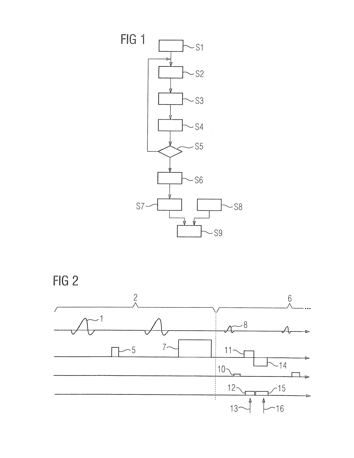
[0042]FIG. 1 shows an exemplary embodiment of a method for determining a B1 field map in a magnetic resonance tomography scanner, the field map describing a local field strength of an alternating RF electromagnetic field radiated by a transmit device to excite nuclear spins for a number of measurement regions disposed in a matrix-like manner. The method will be explained with reference to the measurement sequence schematically illustrated in FIG. 2.

[0043]In step S1, a slice of an object under examination is first prepared, as shown in section 2 of the sequence in FIG. 2. Here a slice selection gradient (not shown) is applied and nuclear spins in a slice of an object under examination are excited by the selected excitation pulse 1. The excitation pulse 1 rotates the magnetization in the center of the excited slice through an assigned flip angle α. The amplitude of the excitation pulse 1 is selected such that the flip angle α is <90°.

[0044]Prior to the radiation of the excitation puls...


PUM


Abstract

In a method and magnetic resonance apparatus for determining a B1 field map in a scanner of the apparatus, the B1 field map describing a local field distribution of a B1 field resulting from excitation pulses radiated in a measurement sequence, first and second measured values are acquired from a region in which nuclear spins are excited by an excitation pulse having an assigned flip angle, and a provisional flip angle is determined from the first and second measured values. A correction factor, dependent on the pulse shape of a selected excitation pulse, is then determined, and the provisional flip angle is multiplied thereby to obtain a corrected value for entry into said B1 field map.

Description

BACKGROUND OF THE INVENTION[0001]Field of the Invention[0002]The invention concerns to a method for determining a B1 field map in a magnetic resonance tomography scanner, the map describing the local field strength of a radiofrequency electromagnetic alternating B1 field radiated by a transmit antenna to excite nuclear spins in at least one measurement region of a subject, wherein, as part of a measurement sequence, the transmit antenna radiates multiple excitation pulses that change the magnetization of an excitation region encompassing the measurement region according to an assigned flip angle, and a first measured value is acquired in a first measuring interval and a second measured value is acquired in a second measuring interval by a reception antenna, the measured values relating to the magnetization in the measurement region, wherein a provisional flip angle value for the flip angle assigned to a selected excitation pulse in the measurement region is determined as a function ...

Claims


Application Information

Patent Timeline
Patent Type & Authority Applications(United States)
IPC IPC(8): G01R33/44G01R33/565G01R33/58
CPCG01R33/443G01R33/5659G01R33/586G01R33/246
Inventor KOEHLER, MICHAEL
Owner SIEMENS HEALTHCARE GMBH
Why Eureka
Try Eureka