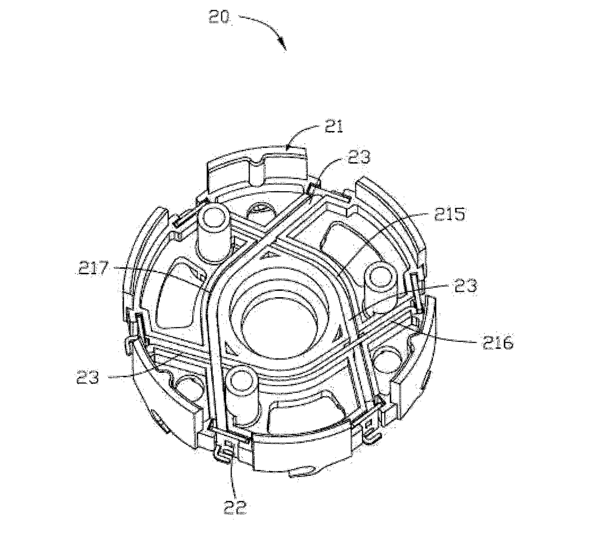
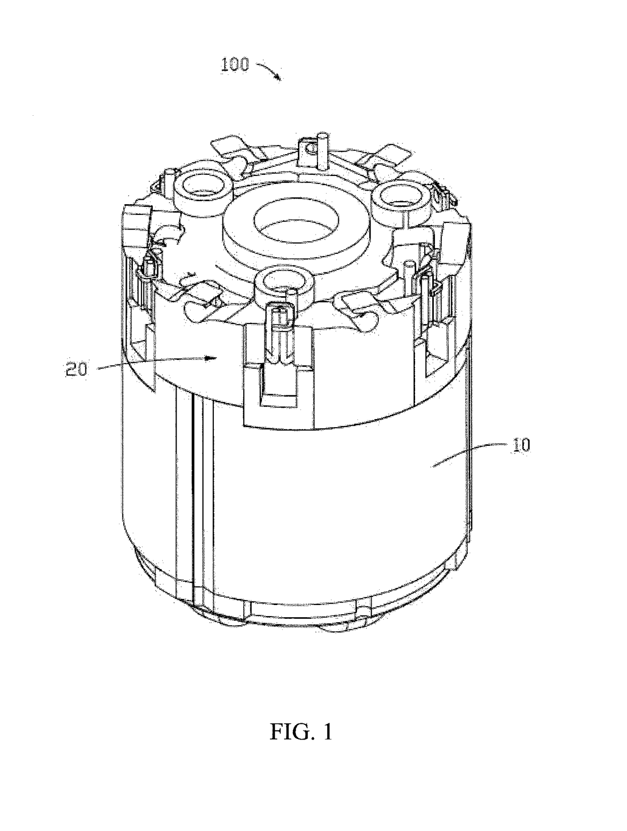
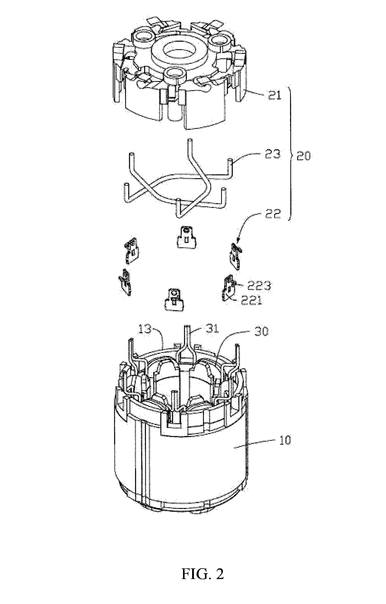
Endcap assembly for an electric motor and stator comprising same

a technology of endcap assembly and electric motor, which is applied in the direction of support/enclose/case, electrical apparatus, dynamo-electric machines, etc., can solve the problems of increasing costs, and achieve the effects of simplifying the connection between the windings, reducing the cost of the motor, and convenient assembly

Inactive Publication Date: 2017-08-24
JOHNSON ELECTRIC SA
View PDF2 Cites 8 Cited by
  • Summary
  • Abstract
  • Description
  • Claims
  • Application Information

AI Technical Summary

Benefits of technology

[0004]Thus, there is a need for an endcap assembly which makes connection of the windings of the motor more convenient and time-saving.
[0019]In the stator according to the embodiments of the present invention, the terminals and wires are fixed on the endcap, which makes it convenient to assemble and makes the best use of the space in the endcap, thereby simplifying the connection between the windings and reducing the cost of the motor. In addition, the endcap defines the accommodating grooves therein and the bosses are formed in the accommodating grooves, such that the wires can be distributed orderly in the endcap without contacting with each other, thereby avoiding intertwining of the wires and the risk of short circuit.

Problems solved by technology

Stator windings of the same phase must be connected together, and a common practice is setting connecting wires on an outer circumferential face of a bobbin (which requires a large radial space), or using PCBA to connect the windings (which increases cost).

Method used


Image

  • Endcap assembly for an electric motor and stator comprising same
  • Endcap assembly for an electric motor and stator comprising same
  • Endcap assembly for an electric motor and stator comprising same

Examples


Embodiment Construction

[0026]The technical solutions of the embodiments of the present invention will be clearly and completely described as follows with reference to the accompanying drawings. Apparently, the embodiments as described below are merely part of, rather than all, embodiments of the present invention. Based on the embodiments of the present disclosure, any other embodiment obtained by a person skilled in the art without paying any creative effort shall fall within the protection scope of the present invention.

[0027]It is noted that, when a component is described to be “fixed” to another component, it can be directly fixed to the another component or there may be an intermediate component, i.e. indirectly fixed to the another component through a third component. When a component is described to be “connected” to another component, it can be directly connected to the another component or there may be an intermediate component. When a component is described to be “disposed” on another component,...


PUM


Abstract

An endcap assembly for an electric motor and a stator having same are provided. The endcap assembly includes an endcap, a first wire, and two terminals corresponding to the first wire. The two terminals are fixed to the endcap and configured to connect with corresponding windings of the electric motor. The endcap defines a first accommodating groove extending from one terminal to the other terminal. The first wire is received in the first accommodating groove, and two ends of the first wire are electrically connected to the two terminals, respectively.

Description

CROSS REFERENCE TO RELATED APPLICATIONS[0001]This non-provisional patent application claims priority under 35 U.S.C. §119(a) from Patent Application No. 201610092346.8 filed in The People's Republic of China on 18 Feb. 2016.FIELD OF THE INVENTION[0002]This invention relates to electric motors, and in particular, to an endcap assembly of the motor.BACKGROUND OF THE INVENTION[0003]Electric Motors are widely used in industrial production and various kinds of electric appliances in our lives. A conventional motor includes a stator and a rotor. A rotary shaft is mounted in the rotor and rotates along with the rotor to thereby output power. Some of the conventional motors have a housing and an endcap. A stator core and stator windings wound on the stator core are mounted in the housing. Stator windings of the same phase must be connected together, and a common practice is setting connecting wires on an outer circumferential face of a bobbin (which requires a large radial space), or using ...

Claims


Application Information

Patent Timeline
Patent Type & Authority Applications(United States)
IPC IPC(8): H02K5/22H02K3/50
CPCH02K3/50H02K5/225H02K1/26H02K3/48H02K3/522H02K2203/06H02K2203/12
Inventor POON, KWONG YIPCHAI, JIEXIAO, SAN YUANLU, KUN ZHOUZHANG, TAO
Owner JOHNSON ELECTRIC SA
Why Eureka
Try Eureka