Warp shedding apparatus of loom

a technology of shedding apparatus and loom, which is applied in the direction of selvedge shedding mechanism, textiles and paper, jacquard, etc., can solve the problems of loom to stop, complicated configuration of loom, and defective wavy selvag

Inactive Publication Date: 2017-08-31
TOYOTA IND CORP
View PDF26 Cites 2 Cited by
  • Summary
  • Abstract
  • Description
  • Claims
  • Application Information

AI Technical Summary

Benefits of technology

[0010]In accordance with an aspect of the present invention, there is provided a warp shedding apparatus of a loom that includes a plurality healds arranged in a weaving width direction of the loom. Each heald has a thread eyelet through which a ground warp yarn is passed and held. In the warp shedding apparatus, the healds are raised and lowered to form a shed....

Problems solved by technology

In such high density fabric, weft yarns tend to be slackened and broken selvages may result at the opposite ends of the fabric in the weaving width direction.
When beaten by the reed, the weft yarn becomes slack and wavy in the portions thereof adjacent to the selvage edges and the stress due to the beating is concentrated in such portions adjacent to the selvage edges, which causes irregularities in the weave structure of the above portions of the fabric adjacent to the selvage edges, resulting in defective wavy selvages.
A weft thus diverted upward and moving away from the gripping yarns fails to be gripped, thus causing the loom to stop.
Such dev...

Method used


Image

  • Warp shedding apparatus of loom
  • Warp shedding apparatus of loom
  • Warp shedding apparatus of loom

Examples


first embodiment

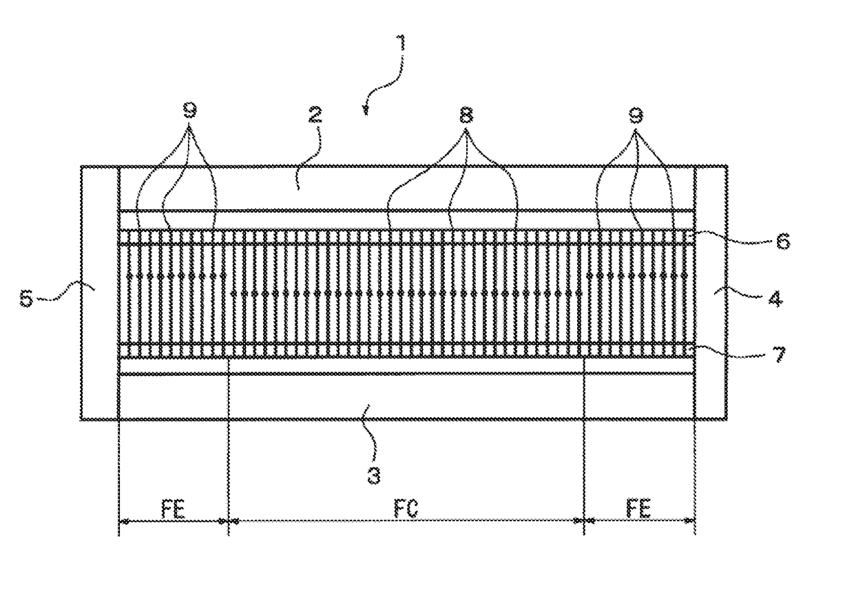
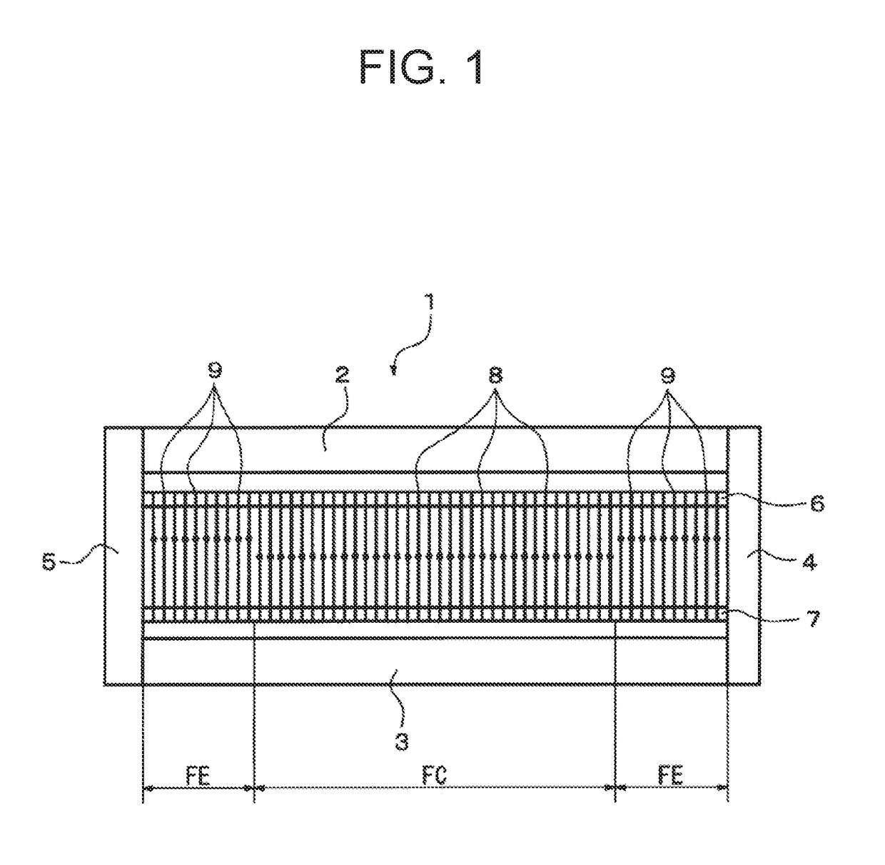
[0019]A first embodiment of the present invention will now be described with reference to FIGS. 1 to 5. Referring to FIG. 1 showing a rectangular heald frame 1 used in a warp shedding apparatus of a loom according to the first embodiment of the present invention, the heald frame 1 includes an upper frame member 2, a lower frame member 3, and side frame members 4 and 5. An upper carrier rod 6 and a lower carrier rod 7 are provided between the upper frame member 2 and the lower frame member 3 and fixed at the opposite ends thereof to the side frame members 4 and 5. The upper carrier rod 6 is located adjacently to the upper frame member 2 and the lower carrier rod 7 is located adjacently to the lower frame member 3.

[0020]A plurality of healds 8 and a plurality of healds 9 are fixed at the opposite ends thereof to the upper and lower carrier rods 6 and 7. The healds 8 are arranged in a segment FC in the central portion of the heald frame 1 in the weaving width direction of the loom and ...

second embodiment

[0044]A second embodiment of the present invention will now be described with reference to FIG. 6. The like reference numerals used in the following description designate the like components in the first embodiment and detailed descriptions on such components will be simplified or omitted. A warp shedding apparatus of a loom according to the second embodiment of the present invention includes a heald frame 19A and a heald frame 19B that is disposed rearward of the heald frame 19A (only the heald frame 19A is shown in FIG. 6). It is so configured that the heald frames 19A and 19B hold only the ground warp yarns 15A and 15B (see FIG. 3) in the side segments FEs, while the ground warp yarns 12A and 12B (see FIG. 3) for the central segment FC are held by the other heald frames (not shown).

[0045]The heald frames 19A and 19B have only healds 20 that are disposed in the segments FEs in the opposite end portions of the respective heald frames 19A and 19B in the weaving width direction of th...


PUM


Abstract

A warp shedding apparatus of a loom includes a plurality healds arranged in a weaving width direction of the loom. Each heald has a thread eyelet through which a ground warp yarn is passed and held. The healds are raised and lowered to form a shed. A difference in tension between raised ground warp yarns and lowered ground warp yarns held by the healds located in opposite end portions in the weaving width direction is greater than a difference in tension between raised ground warp yarns and lowered ground warp yarns held by the healds located in a central portion in the weaving width direction.

Description

BACKGROUND OF THE INVENTION[0001]The present invention relates to a warp shedding apparatus of a loom.[0002]Fabrics that are used for an airbag, a parachute, and the like are woven tightly to have a high density for the specific purposes. In weaving a fabric of high density, a high tension is applied to weft yarns. In such high density fabric, weft yarns tend to be slackened and broken selvages may result at the opposite ends of the fabric in the weaving width direction.[0003]Japanese Unexamined Patent Application Publication No. 9-302550 discloses an improved base fabric for an airbag which does not have loose weft yarns and / or broken selvages. According to the Publication, the base fabric for an airbag is made of synthetic fiber and has a selvage formed of ground yarns and leno yarns, and a plurality of processed reinforcing yarns are added to the selvage.[0004]Generally, the end portion of a selvage in a high density fabric for an airbag may become wavy. Such wavy selvage is spec...

Claims


Application Information

Patent Timeline
IPC IPC(8): D03C3/20
CPCD03C3/20D03C11/00D03C13/00D03C9/00
Inventor YAMAUCHI, YASUSHISUMIYA, KENJI
Owner TOYOTA IND CORP
Why Eureka
Try Eureka