Gas infusion systems for liquids and methods of using the same

a technology of gas infusion system and liquid, which is applied in the direction of watering device, transportation and packaging, rotary stirring mixer, etc., can solve the problems of relative anoxicity and breakup of gas bubbles in water, and achieve the effects of improving irrigation system, increasing crop yield and quality, and accelerating crop developmen

Inactive Publication Date: 2017-09-07
ZOTEXA LLC
View PDF9 Cites 17 Cited by
  • Summary
  • Abstract
  • Description
  • Claims
  • Application Information

AI Technical Summary

Benefits of technology

[0008]The turbine may be freely rotating, and have various designs, such as a gas turbine blade design, Francis turbine blade design, a Kaplan turbine blade design, etc. The cavitating turbine may create microbubbles by multiple mechanisms. First, the shearing forces created by the spinning blades of the cavitating turbine may breakup gas bubbles present in the water as a result of gas injection by the gas injector to create smaller gas bubbles. Second, the cavitating turbine may create new microbubbles by dropping the static pressure of the liquid passing through the conduit to a point that dissolved gases degas to form microbubbles. The rotation of the blades of the cavitating turbine may be driven by the dynamic pressure (the flow) of the liquid passing through the cavitating turbine without any additional driving force applied to the turbine. The size, shape, and number of the turbine blades may have a relationship to the size of the microbubbles created by the turbine at a given dynamic pressure and flow volume. The size, shape, and number of turbine blades can be varied depending on the particular application (e.g., conduit size, dynamic fluid pressure, liquid composition, etc.). In some embodiments, the cavitating apparatus of the present invention may include a plurality of cavitating turbines therein (e.g., the cavitating system may include 3, 4, or more inline cavitating turbines). The plurality of cavitating turbines may be configured such that at least one spins in a clockwise direction and at least one of the plurality of cavitating turbine spins in the opposite direction. It is to be further understood that the fluid delivery system (e.g., subterranean irrigation system) into which the gas-liquid mixture feeds may also include cavitating turbines placed at intervals therein. These additional cavitating turbines may aid in keeping the gas dissolved and suspended in the water column.
[0010]The microbubbles of gas generated by the cavitating system of the present invention are carried as a suspension in a flowing stream. In order for the gas bubbles to stay distributed in solution for a sufficient period of time, they preferably have a diameter within a particular range (about 80 nm to about 1 μm). Microbubbles in that size range may stay distributed in solution, resisting coalescence and degassing. This may be due to balancing between charge force generated at the gas-liquid interface of the microbubble and the surface tension of the liquid. Curved aqueous surfaces may introduce a surface charge due to water's molecular structure, and like charges at the liquid-gas interface will reduce the internal pressure and the surface tension of the liquid as the charge repulsion at the surface of the bubble acts in the opposite direction to the surface tension. These two opposing forces may be at or near an equilibrium in the above-mentioned size-range, and thus coalescence may be resisted. Additionally, buoyancy may be negligible in such microbubbles preventing loss at the top of the liquid column. Thus, the cavitating turbine of the present invention may overcome the tendency of the gas to be released from the liquid or to coalesce, as occurs in conventional systems.
[0019]It is a further object of the present invention to provide a cavitating system for use in irrigation that is operable to infuse an irrigation liquid with oxygen and / or other gases that stay in solution for significantly longer than achieved by conventional systems.
[0021]It is an object of the present invention to provide systems capable of producing significant increases in crop yield and quality, and accelerating the development of crops.

Problems solved by technology

Air delivery is particularly usual for plants that are grown in dense soils, which do not admit much atmospheric oxygen and can become relatively anoxic.
First, the shearing forces created by the spinning blades of the cavitating turbine may breakup gas bubbles present in the water as a result of gas injection by the gas injector to create smaller gas bubbles.
Second, the cavitating turbine may create new microbubbles by dropping the static pressure of the liquid passing through the conduit to a point that dissolved gases degas to form microbubbles.

Method used


Image

  • Gas infusion systems for liquids and methods of using the same
  • Gas infusion systems for liquids and methods of using the same
  • Gas infusion systems for liquids and methods of using the same

Examples


Embodiment Construction

[0033]Reference will now be made in detail to certain embodiments of the invention, examples of which are illustrated in the accompanying drawings. While the invention will be described in reference to these embodiments, it will be understood that they are not intended to limit the invention. To the contrary, the invention is intended to cover alternatives, modifications, and equivalents that are included within the spirit and scope of the invention as defined by the claims. In the following disclosure, specific details are given to provide a thorough understanding of the invention. However, it will be apparent to one skilled in the art that the present invention may be practiced without these specific details.

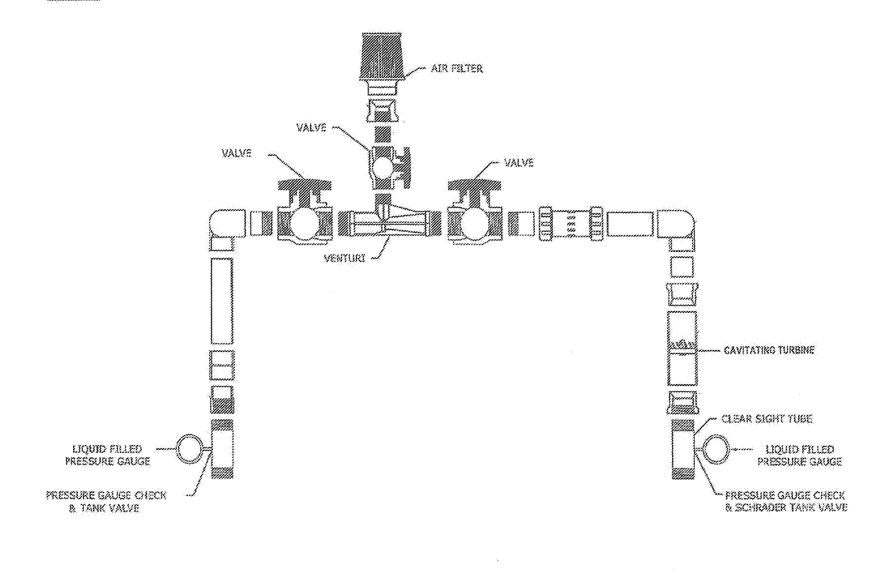
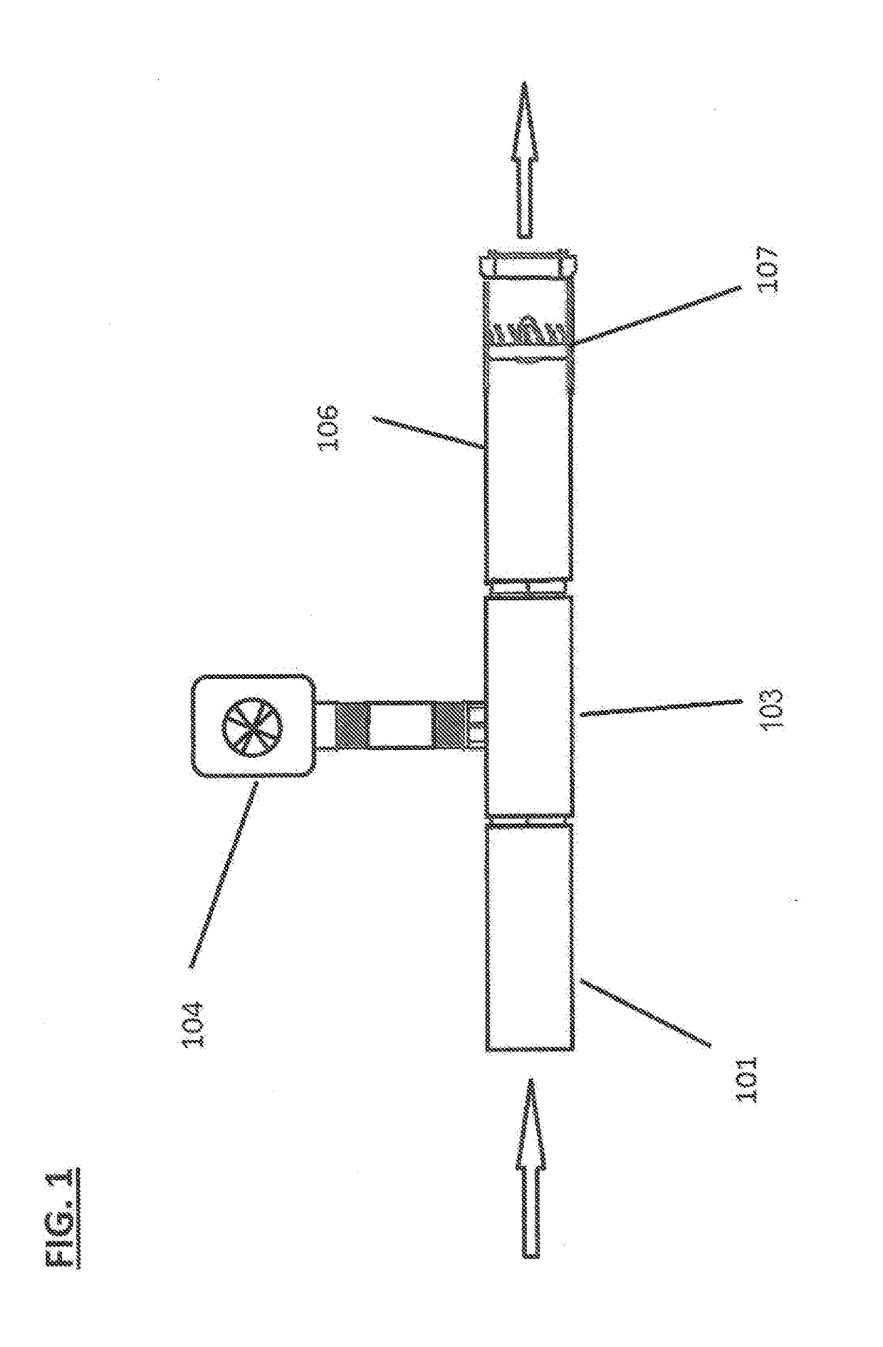
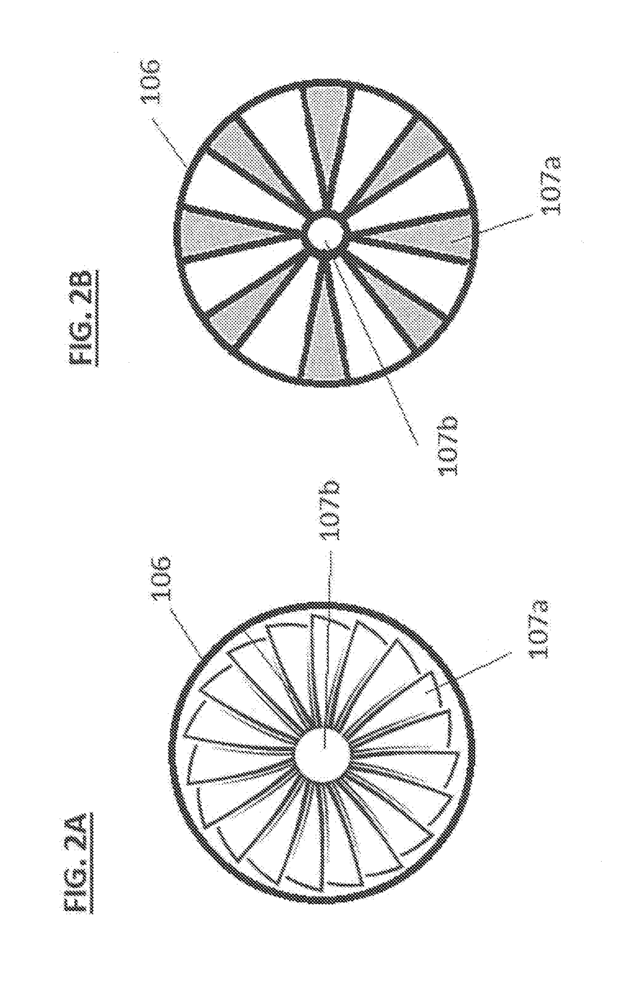
[0034]Referring to the drawings wherein like reference characters designate like or corresponding parts throughout the several views, and referring particularly to FIGS. 1-7, it is seen that the present invention includes various embodiments of cavitating apparatuses, systems ...


PUM

PropertyMeasurementUnit
diameteraaaaaaaaaa
diameteraaaaaaaaaa
diameteraaaaaaaaaa

Abstract

The present invention provides subsurface irrigation systems and air injection mechanism and microbubble generating mechanism. The systems of the present invention are operable to provide an evenly distributed air microbubbles in a stream of fluid (e.g., subsurface irrigation water) to evenly provide gas therein (e.g., oxygen for plants receiving the irrigation water along an entire length of an irrigation line). The microbubble generating mechanism may use pressure generated from flow of fluid to cavitate the fluid and thereby distribute gas microbubbles in the fluid. In irrigation examples, the resulting air infused water delivers an effective amount of oxygen to the roots of the irrigation crops.

Description

FIELD OF THE INVENTION[0001]The present invention relates to mechanisms for infusing liquids with gases, irrigation systems that include such mechanisms, and methods of using the same. More particularly, the present invention relates to microbubble generating mechanisms and there use in irrigation systems and methods of using the same.DISCUSSION OF THE BACKGROUND[0002]Conventional growing procedures for plants and crops include watering by applying water to the soil surface. The applied water includes some dissolved oxygen in it that is carried to the roots by virtue of the water filtering into the soil. The amount of oxygen provided roots by surface watering is not optimal and can be insufficient depending on soil composition. To compensate for the oxygen inefficiencies of surface water, the ground may be permitted to dry in order to admit air into the soil, which may be dissolved and carried to the roots by the next irrigation or watering. This is a tedious and imprecise technique...

Claims


Application Information

Patent Timeline
Patent Type & Authority Applications(United States)
IPC IPC(8): B01F13/10B01F3/04A01G25/16B01F11/02E02B11/00A01G25/06B01F5/04B01F5/16B01F25/64
CPCB01F13/1027B01F5/0415B01F3/0446B01F3/04978B01F3/04106B01F5/16B01F5/162B01F11/0208B01F11/0283E02B11/005A01G25/06A01G25/16B01F2003/04872B01F23/2323B01F23/237611B01F23/23762B01F23/23765B01F25/3121B01F25/31242B01F27/55B01F33/821B01F23/231B01F23/232B01F23/238B01F25/64B01F25/641B01F31/81B01F31/87B01F23/2326
Inventor BENNETT, TYLERROSENFELD, OFER
Owner ZOTEXA LLC
Why Eureka
Try Eureka