Orbital Welder With Integrated Track And Gear Drive

a welder and gear drive technology, applied in the field of welding, can solve the problems of various limitations of the related art, inability to operate under orbital welding devices, and inability to meet the requirements of orbital welding devices, and achieve the effect of convenient repositioning and easy engagemen

Active Publication Date: 2017-09-07
BHI ENERGY I SPECIALTY SERVICES LLC
View PDF11 Cites 19 Cited by
  • Summary
  • Abstract
  • Description
  • Claims
  • Application Information

AI Technical Summary

Benefits of technology

[0025]It is an object of the invention to provide an easily removably positionable orbital welding device for joining tubes pipes and fittings.
[0026]It is an object of the inventio

Problems solved by technology

A significant shortcoming of conventionally available orbital welders for pipe and tubing and the like, is the inability to for conventional devices to operate under conditions where the orbital welding device must operate with tight clearan

Method used


Image

  • Orbital Welder With Integrated Track And Gear Drive
  • Orbital Welder With Integrated Track And Gear Drive
  • Orbital Welder With Integrated Track And Gear Drive

Examples


Embodiment Construction

[0040]In this description, the directional prepositions of up, upwardly, down, downwardly, front, back, top, upper, bottom, lower, left, right and other such terms refer to the device as it is oriented and appears in the drawings and are used for convenience only and they are not intended to be limiting or to imply that the device has to be used or positioned in any particular orientation.

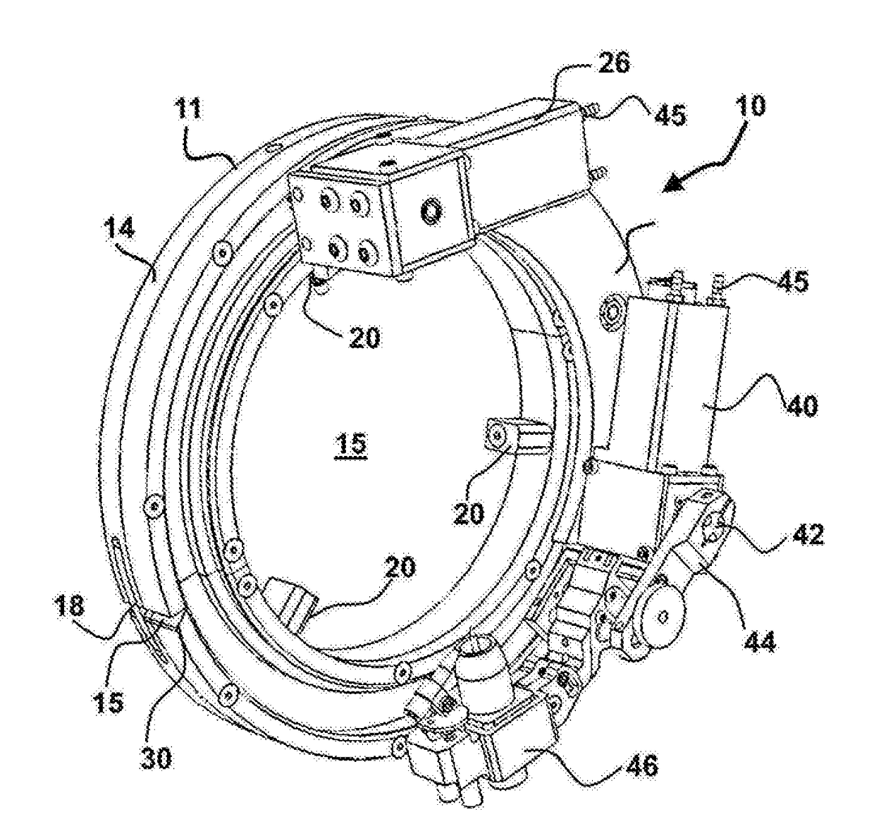
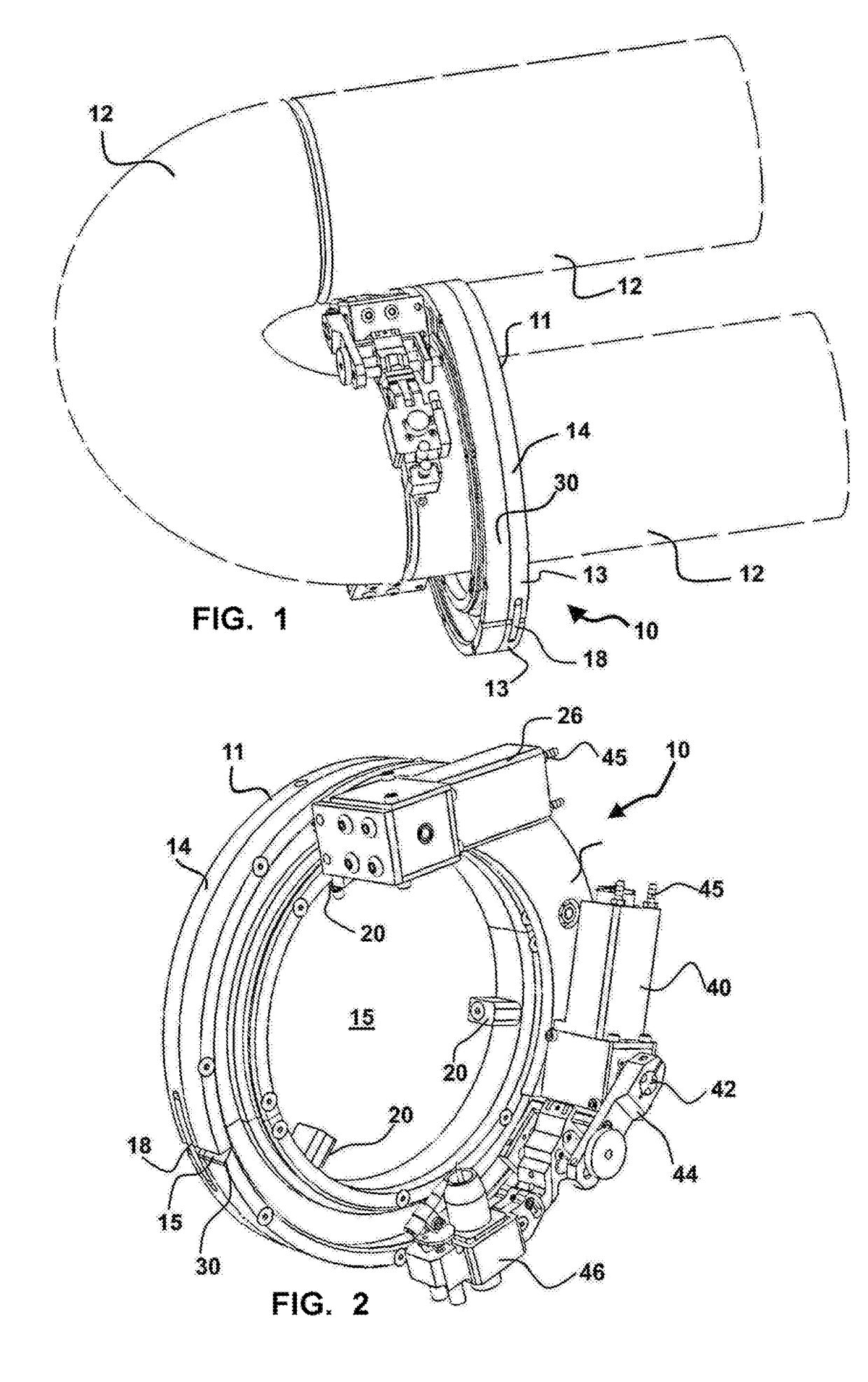
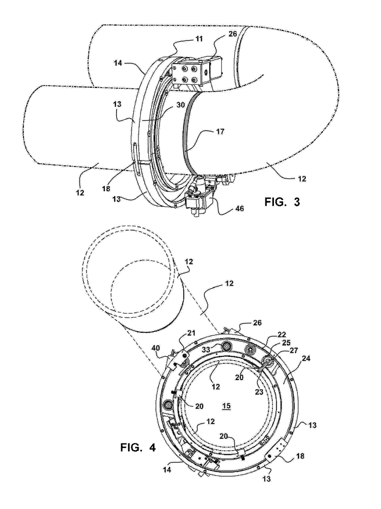
[0041]Now referring to drawings in FIGS. 1-10, wherein similar components are identified by like reference numerals, there is seen in FIG. 1 the FIG. 1, the orbital welding device 10 herein. As shown the device 10 forms an assembly 11 when assembled and operatively engaged upon one of two adjoining segments to be welded, such as pipe 12, to an as-used position operatively engaged with one of two pipes 12 or fittings for welding abutted edges thereof.

[0042]As shown in the drawings herein, the device 10, is formed to an assembly 11 which includes a track ring 14. This track ring 14 as better shown in...


PUM

PropertyMeasurementUnit
Distanceaaaaaaaaaa
Circumferenceaaaaaaaaaa

Abstract

An orbital welding device for forming a circumferential weld bead to engage adjoining segments of pipe is provided. The device features an annular track ring having an opening for engagement around the pipe. A travel carriage rotationally engaged with the annular track ring has a first motor for rotating the travel carriage and an engaged welding head around the pipe for forming a weld thereon. A second motor is provided to adjust a distance of the welding head from the pipe.

Description

BACKGROUND OF THE INVENTION[0001]1. Field of the Invention[0002]This application claims priority to U.S. Provisional Patent Application Ser. No. 62 / 303,955, filed on Mar. 4, 2016, which is incorporated herein in its entirety by this reference thereto.[0003]The present invention relates generally to welding. More particularly it relates to a welding device configured for orbital welding of pipe to pipe joint and fitting welds which employs an integrated track with gear drive which is adapted for circumferential engagement with the exterior of pipes being welded. So engaged, the integrated configuration will operate under axial and radial constraints which are heretofore unavailable in such welding devices.[0004]2. Prior Art[0005]In industries employing pipe and tubes for carrying liquids and gases, a conventional method for joining two abutting tubular segments, such as pipes or tubes or fittings engaged therewith, is to butt the respective ends of the segments to be joined, and orbi...

Claims


Application Information

Patent Timeline
IPC IPC(8): B23K9/00
CPCB23K2201/10B23K9/0052B23K9/0286B23K9/16B23K37/0217B23K37/0282B23K2101/06B23K2101/10
Inventor CASH, SHANE
Owner BHI ENERGY I SPECIALTY SERVICES LLC
Why Eureka
Try Eureka